What you put in, you'll get back ten fold
***** THIS IS VERY IMPORTANT TO THE SITE AND HELPING YOU,OTHERWISE IT CLOSES AND ALL THIS ON LINE GARAGE IS GONE FOR GOOD*****

Greetings and welcome to menders, this site was built for every owner that might need her to help keep those bills low and also keep them on the road where they belong, she is run by very passionate enthusiasts owners for passionate enthusiastic owners, see her like a on line garage, there is a lot of tech stuff hopefully explained for everyone to use, if there is something you cannot get your head around, or you feel that there is a strong walk through guide missing that needs creating by one of us or from yourselves, please let us know, we are also on false book and youtube, which as short tech vids to help, and again if you feel there is a vid that would help please get it touch.
the menders is free, but like everything there is a cost to run things and bills( we are just happy its not a heating cost), so if we have saved you hundreds, please throw a small donation in the pot so we can keep on going to carry on helping others in the same way .

*** we are currently looking for a sponsor for this year, so if you have the passion and can see this sites worth to everyone , please get in touch and step forward to help***

And thank heavens that we are now on the way back up the brighter ,warmer longer days, "come on summer", and lets see those project builds.


M-m

MK 1 NA 1.6 SNC/LNC water pump/cam belt change/cam/crank seals etc

User avatar
Mazda Mender
Site Admin
Posts: 15090
Joined: Tue Dec 06, 2011 6:18 pm
Location: Pie land, in the glen of Wiganshire
Contact:

MK 1 NA 1.6 SNC/LNC water pump/cam belt change/cam/crank seals etc

Postby Mazda Mender » Mon Apr 15, 2019 6:59 am

*****SECTION ONE*****


*****Clicking on the images will enlarge for better viewing*******


Although this walk through guide was done using a early MK 1 NA LNC 1.6 version , there are only slight differences for the MK 1 NA 1.6 SNC, MK 1 NA 1.8, Mk 2 NB 1.6/1.8 and the MK 2.5 MBFL 1.6/1.8VVT. I will cover and explain all versions across the water pump and cam belt change guides showing the differences etc. and parts, tools needed to be able to do so on the other versions. I will be adding more advice and info over time until I have covered everything...

This may look a daunting task but I have tried to show everything so you can use this as a step by step and a step back guide also for bits that were forgotten as you take the engine apart and rebuild. Just see this as a great big jigsaw puzzle but a very important one to be done correctly and right first time.
It is worth either loaning the correct locking tools from the owners club if you are a member, or just buying them as they are not expensive. If you are doing it yourself, it still well outweighs the cost the whole job would be if taking it to a Mazda dealership or a independent specialist. With these two seater roadsters the biggest cost is the labour costs, plus if you are doing this yourself, I guarantee you will find all those extra little jobs to do as you go, like spraying the pulley wheel etc etc 100%, so you can take your time.
The guide is broken into sections, so hopefully it will be be easier to understand and follow..

Torque settings...
https://www.miata.net/garage/torque.html

Torque settings PDF for down loading if needed>>>>>>>>>>>
Torque (6).pdf
(34.03 KiB) Downloaded 265 times


All parts were kindly supplied by our friend and sponsor for 2019 Autolinkmx5 for this guide, members of the Menders board do get discount with them if needed... https://www.autolinkmx5.com/mazda-mx-5-parts-8-c.asp

Section one is a introduction (this section),
Section two is the strip down,
Section three is the rebuild,
Section four is up and running checks etc......

-----------------------------------------------------------------------------------------------------------------------------------------------------------------------------

Parts Needed...

2.5 Ltrs of concentrated or 5 Ltrs of ready mixed coolant
2.5 Ltrs of Deionised water if using concentrated coolant
Water pump, ( with both gaskets and inlet O'ring seal)
Idler,
Tensioner,
Tensioner spring,
Cam/Timing belt,
Cam seals,
Crank seal,
Rocker cover seal,
CAS seal,(MK 1 only),
Rear large union copper washer seals x 2( MK 2 VVT only),
New crank bolt and new woodruff key( Mk 1 1.6 SNC only)
Service items to be done at the same time is down solely to your choice, we recommend doing it all at the same time, job done, Aux belts, plugs,filters etc...

-------------------------------------------------------------------------------------------------------------------------------------------------------------------------


Tools needed....
Large breaker bar,
small breaker bar,
1/2" Drive ratchet and extensions,
1/2" 21mm,14mm sockets,
3/8 Drive ratchet and extensions,
3/8 10mm socket,
1/4 Drive ratchet and extensions,
1/4 12mm ,10mm sockets,
10mm,12mm,14mm ring and open spanners (ratchet spanners will help but not needed),
21mm ratchet spanner or similar,
Phillips drivers,
Large and small hammers,
Long whacker bar,
Long nose pliers or standard pliers,
Small flat driver or pick,
Gasket scrapers ,
Small bungee cord or piece of robe etc,
Hose seal removal tool,
Hook tool for removing the old seals,
Small hook/pick for the CAS seal,
Wire brush (if needed),
Coolant catch container,
Paint pen or tipex ,
Cam lock ( Jass performance tool used) Or two large 1" open end spanners or two large 23mm spanners ( depending on the cast Nut on the cam shafts) and locking mole grips,
Crank lock ( Junk yard dogs tool used),
Copper grease,
Lithium grease,
Silicon spray,
Easit spray,
Crank seal tool ( Jass performance tool used),
Cam seal tool ( short piece of plastic pipe),
Gloves,
Rags,
Fine sand paper,

IMG_20190413_185320.jpg
IMG_20190413_185320.jpg (740.67 KiB) Viewed 4319 times


IMG_20190413_185812.jpg
IMG_20190413_185812.jpg (509.52 KiB) Viewed 4319 times

------------------------------------------------------------------------------------------------------------------------------------------------------
Now there are two types of water pumps for the Roadsters from 1989 to 2005..

MK 1 1.6 early and late versions( pics are for reference).....
Note the tensioner bolt hole is threaded and no extra lug for the alternator bracket..

water-pump-mazda-mx-5-mk1-1.6-1989-98-waterpump-with-gaskets-gmb-made-in-japan-[4]-9889-p.jpg
water-pump-mazda-mx-5-mk1-1.6-1989-98-waterpump-with-gaskets-gmb-made-in-japan-[4]-9889-p.jpg (382.77 KiB) Viewed 4319 times


NM00094-GMBb.jpg
NM00094-GMBb.jpg (398.07 KiB) Viewed 4316 times


This kit is missing the rocker cover seal and CAS seal...
T80836202.jpg
T80836202.jpg (19.3 KiB) Viewed 4319 times


Mk 1 1.8, MK 2 1.6/1.8,MK 2.5 1.6/1.8 VVT( pics are for reference)....

Note that the tensioner hole is not threaded and the extra lug bolt hole for the alternator bracket...

s-l1600.jpg
s-l1600.jpg (398.9 KiB) Viewed 4319 times


water-pump-mazda-mx-5-mk1-1.8-all-mk2-mk2.5-waterpump-with-gaskets-759-p.jpg
water-pump-mazda-mx-5-mk1-1.8-all-mk2-mk2.5-waterpump-with-gaskets-759-p.jpg (422.48 KiB) Viewed 4319 times


This kit is missing the CAS O'ring seal for the MK 1....
F76440783.jpg
F76440783.jpg (299.7 KiB) Viewed 4319 times


----------------------------------------------------------------------------------------------------------------------------------------------
Long Nose Crank (LNC) compared to Short Nose Crank (SNC)
Now the short nose crank and the long nose crank identification on the early MK 1 1.6 versions....
There is a lot of ill informed info on this subject, in that the SNC is the weakest and the most prone to fail with key wear/crank shaft wear, can I just put that record straight...it is a load of tosh, they can "ALL fail in the same way, to which I have dealt with many of all years and engine sizes, it is solely down to the think they know it all spanner monkey that has done the job incorrect to bring on the problem, not the way they are engineered or made , and let me state this again...it is not souly centred to the SNC as the mass of ill informed like to preach freely from " I read it somewhere" ..or I heard it off someone, somewhere" or "I have only worked on my own so I know", it is down to the unacknowledged doing them incorrect 100%, sorry if this upsets the preachers of incorrect advice and information and hurt your feelings.

There is NO NEED to undo and remove the crank bolt in a SNC engine to do the cam belt and water pump. Please make sure you understand the differences between them and the do's and don'ts. The myth's of the SNC engines being the worst for failing is a load of tosh, the reason they get crank wear and fail is simply because of "have a go" heroes that have not done their home work correctly, be it a garage or home spanner thrower. When doing a cam belt change they removed the bolt and reused it, but wrongly to the later torque settings and over stretched the bolt which works itself loose bringing on wear to the crank key way and woodruff key (crank shaft key) and killed the engine and are then looking at something else to blame but god forbid themselves...The SNC set up was short lived ( 1989 - Aug 1990) and was changed to the LNC from 1990 > 1997 then the BNC was used and that set up stayed to 2005.
We recommend that "if" you do need to remove the SNC engine bolt to replace a leaking crank seal, you buy and fit a new crank bolt and Woodruff key using heavy duty thread lock and torquing up to the correct (lesser) setting than the long nose crank, and let the thread lock cure. Do this and you should not have any issues. Don't be afraid to work on or use a SNC version , I would have one any day.
The easiest and quickest way to identify the difference is by the crank pulley which as 4 slots and a V belt alternator groove....

SNC 1989 - Aug 1990 crank bolt.....Torqued to 80-87 ft lb/108-118 NM ( with heavy duty thread lock and left to cure)

pulley-crankshaft-outer-mazda-mx-5-1.6-mk1-1989-90-lwsc-4-slot-b6s711401a-new-4028-p.jpg
pulley-crankshaft-outer-mazda-mx-5-1.6-mk1-1989-90-lwsc-4-slot-b6s711401a-new-4028-p.jpg (397.11 KiB) Viewed 4316 times


crankshaft01 (1).jpg
crankshaft01 (1).jpg (15.72 KiB) Viewed 4316 times


$_1.jpg
$_1.jpg (20.16 KiB) Viewed 4310 times


The MK 1 LNC pulley is identified by a 8 slot pulley..., V groove on the 1.6...

LNC 1991 - 2005 crank bolt.....Torqued to 116-122 FT lb/157-165 NM ( there is no need for thread lock, but can be used if wished)

long-nose-crankshaft-pulley-mazda-mx5-mk1.jpg
long-nose-crankshaft-pulley-mazda-mx5-mk1.jpg (13.65 KiB) Viewed 4316 times


$_1.jpg
$_1.jpg (20.16 KiB) Viewed 4310 times


The MK 1 LNC 1.8 crank pulley from 1993 to 1997 both are Multi rib aux belts.....

94-05 Mazda Miata Crankshaft - BPD4-11-401.jpg
94-05 Mazda Miata Crankshaft - BPD4-11-401.jpg (409.18 KiB) Viewed 4238 times


28.jpg
28.jpg (67.58 KiB) Viewed 4238 times


2010-12-23_021803_tb.gif
2010-12-23_021803_tb.gif (28.51 KiB) Viewed 4238 times


There are 2 types of mk2 crank pulley, the pressed one and the cast one, there seems no rhyme or reason as to which one is fitted, you just have to see what's on the car. People prefer the pressed one as it's lighter and less brittle.

The LNC 1.6 MK 2/2.5 crank pulley from 1998 to 2005 both are multi rip aux belts...

PRESSED.....
The boss is the same on both...
DSC_0648.jpg
DSC_0648.jpg (505.3 KiB) Viewed 4237 times


The MK 2 LNC 1.8 crank pulley from 1998 to 2000 both are multi rip Aux belt....

CAST.....
The boss is the same on both...
98 to 00.jpg
98 to 00.jpg (20.35 KiB) Viewed 4238 times


The MK 2.5 LNC 1.8 VVT crank pulley from 2001 to 2005 both are a multi rip belts....

IMG_20190525_095253.jpg
IMG_20190525_095253.jpg (532.5 KiB) Viewed 4237 times


IMG_20190525_095256.jpg
IMG_20190525_095256.jpg (526.76 KiB) Viewed 4238 times


IMG_20190525_095259.jpg
IMG_20190525_095259.jpg (481.23 KiB) Viewed 4238 times


IMG_20190525_095328.jpg
IMG_20190525_095328.jpg (567.15 KiB) Viewed 4238 times


Difference between the LNC/ SNC crank bolts...

IMGP4454.jpg
IMGP4454.jpg (461.09 KiB) Viewed 4310 times


SNC....
Figure1a.jpg
Figure1a.jpg (6.45 KiB) Viewed 4310 times


LNC..

Figure3a.jpg
Figure3a.jpg (6.75 KiB) Viewed 4310 times


BNC...

big-nose-crankshaft-diagram.jpg
big-nose-crankshaft-diagram.jpg (3.45 KiB) Viewed 4250 times


Difference between the SNC and LNC crank cogs...

SNC Cog.....

s-l500.jpg
s-l500.jpg (17.34 KiB) Viewed 4251 times


LNC cog.....

M108834436.jpg
M108834436.jpg (4.68 KiB) Viewed 4251 times


Difference between the SNC and LNC woodruff keys..

SNC key....

M108832616.jpg
M108832616.jpg (10.7 KiB) Viewed 4251 times


LNC key....

M108833332.jpg
M108833332.jpg (2.65 KiB) Viewed 4251 times


Extra bits needed to do the 1.8 VVT cam belt replacement....

2 x copper washers for the large union on the oil feed pipe on the back of the engine( Ref 10-333)...

10-333.jpg
10-333.jpg (49.14 KiB) Viewed 4251 times


DSC_1781-500x331.jpg
DSC_1781-500x331.jpg (36.24 KiB) Viewed 4251 times


DSC_1782-500x331.jpg
DSC_1782-500x331.jpg (27.37 KiB) Viewed 4251 times


post-617-0-35312500-1366643431.jpg
post-617-0-35312500-1366643431.jpg (12.91 KiB) Viewed 4237 times


305869L.gif
305869L.gif (28.78 KiB) Viewed 4237 times


03000401 (1).jpg
03000401 (1).jpg (25.83 KiB) Viewed 4237 times


If you have found this guide to be useful, helpful or as helped you with your roadster with saving on garage costs , please consider making a donation to keep these gates open and available for others and so new info can still be added to carry on helping.
The Disclaimer:-
This post is a natural product made from recycled electrons. The slight variations in spelling and grammar enhance its individual character and beauty and in no way are to be considered flaws or defects, the articles/answers/comments are provided for information purposes and they are not intended to substitute informed professional advice, I or mazdamenders.net cannot personally be hold responsible for any damage occurred from following this procedure or any injuries from it. Proceed at your own risk.


Mk 1 Eunos 93 black V.S II 1.8 ,
Mk 2 .1/4 Roadster 99 black & gold V.S 1.8 .
Mk 1 Eunos 90 1.6 soul red ..f/ build
MK 2.1/4 Blue V.S Roadster 1.8 99 ..
MK1 1.8 ,white import.. (Ashleighs)
MK1 1.6 yellow J ltd import.f/build
MK 1 1.8 black Tokyo Ltd..f/build


http://www.mx5oc.co.uk/ http://www.mx5nutz.com/forum/ http://miata.net/ http://www.autolinkuk.co.uk/
User avatar
Mazda Mender
Site Admin
Posts: 15090
Joined: Tue Dec 06, 2011 6:18 pm
Location: Pie land, in the glen of Wiganshire
Contact:

Re: MK 1 NA 1.6 LNC/SNC water pump/cam belt change

Postby Mazda Mender » Wed May 08, 2019 7:57 am

***SECTION TWO :- the strip down..***

*****Clicking on the images will enlarge for better viewing*******

As mentioned in section one we are using a MK 1 NA 1.6 LNC Eunos Roadster import 1992 for this walk through guide.. MK 1 NA 1.6 SNC info will be added....

Keep your working space safe and clear , protect the wings and nose cone, if need be a selection of metal magnetic trays will help in storing the number of nuts and bolts etc or lube spray can oil lids. You will need a large tub to catch the drainage of antifreeze, a 25 ltr container will work easy enough for this .... Follow link....viewtopic.php?f=91&t=7179 ( please dispose of the old coolant correctly).
Have all your service bits to hand and tools ( depending on which model version) as mentioned in Section One...

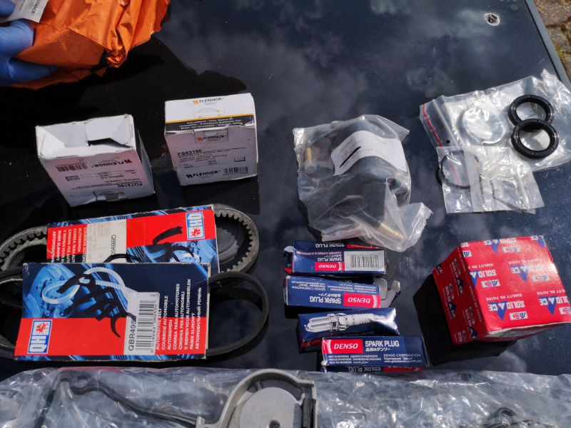
Your new items.. pump,seals,belt and bearings( we were doing a service also)....

IMG_20190413_152543.jpg
IMG_20190413_152543.jpg (685.65 KiB) Viewed 4302 times


IMG_20190413_152548.jpg
IMG_20190413_152548.jpg (562.03 KiB) Viewed 4302 times


IMG_20190413_152552.jpg
IMG_20190413_152552.jpg (613.16 KiB) Viewed 4302 times


IMG_20190413_152557.jpg
IMG_20190413_152557.jpg (595.6 KiB) Viewed 4302 times


Tools for the attack..

IMG_20190413_185304.jpg
IMG_20190413_185304.jpg (751.94 KiB) Viewed 4302 times


IMG_20190413_185320.jpg
IMG_20190413_185320.jpg (740.67 KiB) Viewed 4302 times


IMG_20190413_185812.jpg
IMG_20190413_185812.jpg (509.52 KiB) Viewed 4302 times


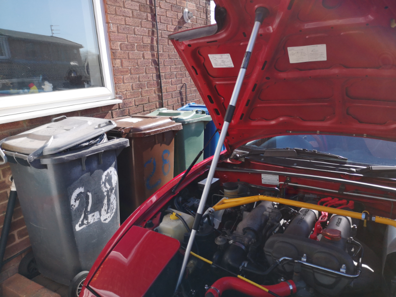
*****PLEASE DO NOT DO THIS WATER PUMP AND BELT CHANGE ON A HOT ENGINE*******


Pop the bonnet and support safely so it does not become a guillotine or large mouse trap. It might be alloy but if it drops on your head or hands..it will hurt 100%. A good gust of wind can dislodge it off the prop or it can easily be knocked while working under there, so please just be mindful.

IMG_20190413_100747.jpg
IMG_20190413_100747.jpg (532.47 KiB) Viewed 4302 times


IMG_20190413_100811.jpg
IMG_20190413_100811.jpg (532.33 KiB) Viewed 4302 times


IMG_20190413_101006.jpg
IMG_20190413_101006.jpg (544.54 KiB) Viewed 4302 times


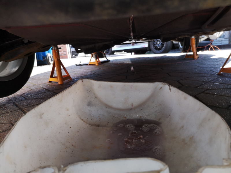
We had her on axle stands for other work being carried out, but it does make the job easier, personal choice... Now the container to catch the coolant needs to go underneath where the radiator drainage plug is...

IMG_20190413_101623.jpg
IMG_20190413_101623.jpg (576.29 KiB) Viewed 4302 times


IMG_20190413_101648.jpg
IMG_20190413_101648.jpg (425 KiB) Viewed 4302 times


IMG_20190413_101657.jpg
IMG_20190413_101657.jpg (597.83 KiB) Viewed 4302 times


Leave the rad cap tight for the minute, do not undo it as it is acting as a vacuum while we undo the drainage plug by way of a Phillips driver. The larger the screwdriver the better to get a good grip on the soft plastic plug. If it decides to not play and undo...this is is how to get it out. Link>>>>>>>> https://www.youtube.com/watch?v=FZZhlQDyvDw&t=23s

IMG_20190413_101718.jpg
IMG_20190413_101718.jpg (373.57 KiB) Viewed 4295 times


IMG_20190413_101952.jpg
IMG_20190413_101952.jpg (690.46 KiB) Viewed 4295 times


Once removed it should just trickle out while it is still under vacuum...

IMG_20190413_101956.jpg
IMG_20190413_101956.jpg (438.02 KiB) Viewed 4295 times


Then remove the rad cap and it will pour out....

IMG_20190413_115637.jpg
IMG_20190413_115637.jpg (457.19 KiB) Viewed 4294 times


IMG_20190615_121451.jpg
IMG_20190615_121451.jpg (507.89 KiB) Viewed 4280 times


IMG_20190413_102009.jpg
IMG_20190413_102009.jpg (468.35 KiB) Viewed 4295 times


Once it has finished draining....

IMG_20190413_115626.jpg
IMG_20190413_115626.jpg (531.16 KiB) Viewed 4295 times


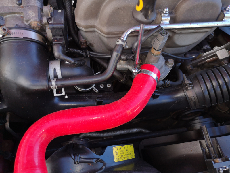
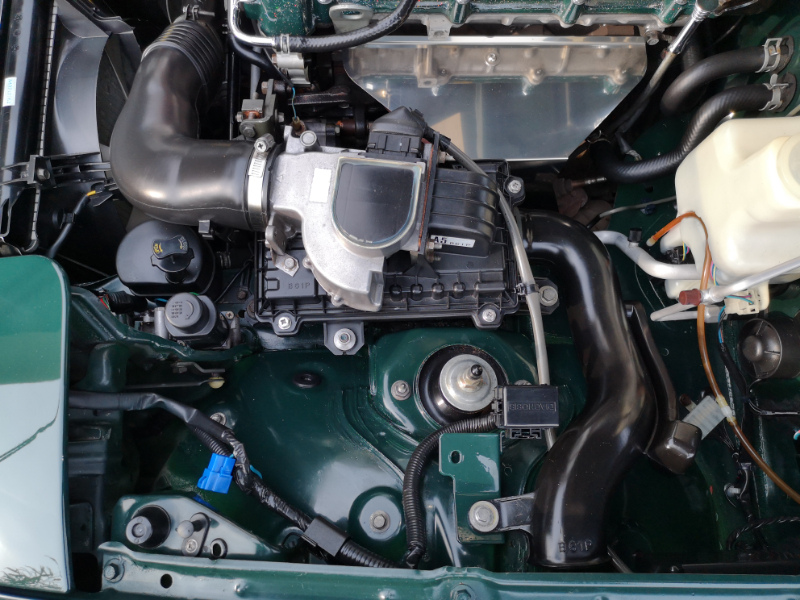
We can move onto the top radiator hose, now with the 1.6 MK 1 versions the air intake trunking runs under the top rad hose to the filter box so the hose needs to be removed first .


Now depending on the hoses used, OE or silicon can depend on which hose clamps have been used,,,Mazda OE spring loaded clips from the Devil or after-market jubilee clips..

If they are OE clips from the Devil ( But are better than jubilee clips), get a pair of pliers and squeeze the clip ends together and move the clip into the middle of the hose at both ends, if it is a after-market jubilee clip you can use a phillps driver, flat driver or a 1/4 drive ratchet with a extension and in most cases a 7 mm socket to loosen them and move them into the middle of the hose ...

IMG_20190413_102058.jpg
IMG_20190413_102058.jpg (507.52 KiB) Viewed 4294 times


IMG_20190413_102103.jpg
IMG_20190413_102103.jpg (544 KiB) Viewed 4294 times


IMG_20190413_102133.jpg
IMG_20190413_102133.jpg (570.77 KiB) Viewed 4294 times


DEVIL CLIPS....

IMG_20190615_121215.jpg
IMG_20190615_121215.jpg (482.72 KiB) Viewed 4280 times


IMG_20190615_121218.jpg
IMG_20190615_121218.jpg (547.82 KiB) Viewed 4280 times


IMG_20190615_121230.jpg
IMG_20190615_121230.jpg (535.35 KiB) Viewed 4280 times


IMG_20190615_121303.jpg
IMG_20190615_121303.jpg (459.36 KiB) Viewed 4280 times


IMG_20190615_121353.jpg
IMG_20190615_121353.jpg (477.74 KiB) Viewed 4280 times


IMG_20190615_121409.jpg
IMG_20190615_121409.jpg (533.54 KiB) Viewed 4280 times


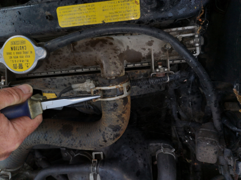
Then we need to remove the hose, please be careful if you are not using a hose seal removal tool that you do not damage the hoses if they are going to be reused. If like in this case we were replacing all the hoses and radiator anyhow, we did not need to worry. Plus now would be a very good time to check that the coolant hoses are not dry and hard which means they are well past their best and need replacing. The hoses we used were from Autolinkmx5 if anyone is wondering for this guide.

Our seal breaker tool....

IMG_20190413_103529.jpg
IMG_20190413_103529.jpg (492.36 KiB) Viewed 4294 times


Which just is fed into the end of the hose and pushed all the way around to break the seal between the hose and unit...

IMG_20190413_103511.jpg
IMG_20190413_103511.jpg (479.19 KiB) Viewed 4294 times


IMG_20190413_103520.jpg
IMG_20190413_103520.jpg (529.23 KiB) Viewed 4294 times


Then just remove the hose and put it safe....

IMG_20190615_121435.jpg
IMG_20190615_121435.jpg (510.74 KiB) Viewed 4280 times


IMG_20190615_121439.jpg
IMG_20190615_121439.jpg (561.07 KiB) Viewed 4280 times


******PLEASE NOTE>>>>>THERE IS NO NEED TO REMOVE THE RADIATOR TO DO THE BELT AND PUMP CHANGE*******


Now we need to remove the air trunking on the MK 1 1.6 versions......

Get your medium Phillips turner outer or 1/4 drive 10 mm socket,extension and ratchet and loosen the holding clips on the AFM and Throttle body...


IMG_20190413_115656.jpg
IMG_20190413_115656.jpg (338.02 KiB) Viewed 4294 times


IMG_20190413_120132.jpg
IMG_20190413_120132.jpg (522.97 KiB) Viewed 4294 times


IMG_20190413_120147.jpg
IMG_20190413_120147.jpg (454.04 KiB) Viewed 4294 times


AFM...

IMG_20190413_115650.jpg
IMG_20190413_115650.jpg (526.6 KiB) Viewed 4294 times


Throttle body....

IMG_20190413_115705.jpg
IMG_20190413_115705.jpg (508.84 KiB) Viewed 4294 times


Now get your long nose pliers or choice of tool and we need to loosen the OE Devil clips ...

IMG_20190413_115736.jpg
IMG_20190413_115736.jpg (466.98 KiB) Viewed 4294 times


IMG_20190413_115746.jpg
IMG_20190413_115746.jpg (516.37 KiB) Viewed 4294 times


IMG_20190413_115754.jpg
IMG_20190413_115754.jpg (470.78 KiB) Viewed 4294 times


IMG_20190413_115801.jpg
IMG_20190413_115801.jpg (468.01 KiB) Viewed 4294 times


IMG_20190413_115806.jpg
IMG_20190413_115806.jpg (421.41 KiB) Viewed 4294 times


Now we need to remove the 10 mm head bolt that holds the air intake to engine...Now this will test you and loves nothing more than dropping off into the depths of the engine bay. So be ready once undone to catch it and bring it clear and safe. 1/4 drive ratchet, extension and 10 mm socket again for this....

IMG_20190413_120157.jpg
IMG_20190413_120157.jpg (439.22 KiB) Viewed 4294 times


IMG_20190413_120207.jpg
IMG_20190413_120207.jpg (460.13 KiB) Viewed 4294 times


IMG_20190413_120243.jpg
IMG_20190413_120243.jpg (458.38 KiB) Viewed 4294 times


Now the air trunking is loose enough to remove the breather hoses free from the trunking...

IMG_20190413_120314.jpg
IMG_20190413_120314.jpg (438.24 KiB) Viewed 4294 times


IMG_20190413_120333.jpg
IMG_20190413_120333.jpg (449.96 KiB) Viewed 4294 times


IMG_20190413_120337.jpg
IMG_20190413_120337.jpg (473.87 KiB) Viewed 4294 times


IMG_20190413_120448.jpg
IMG_20190413_120448.jpg (398.82 KiB) Viewed 4294 times


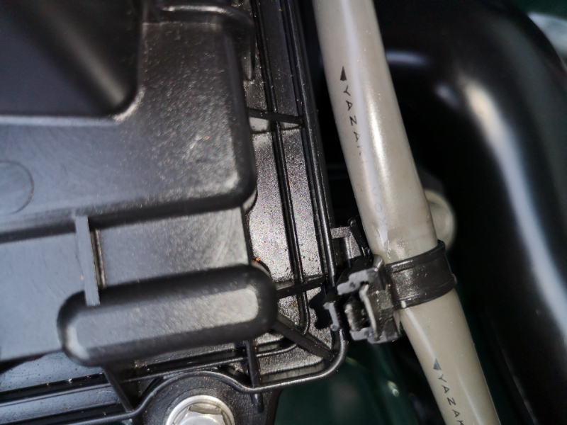
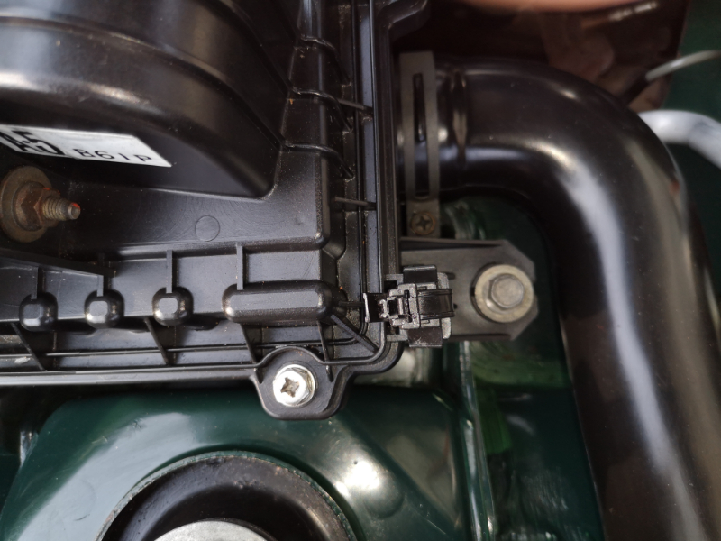
Now there is one more plastic clip we need to undo to be able to pull the trunking free from the roadster, which secures the loom nice and tidy so it does not catch a AUX belt, it is on the back on the drivers side as we are looking into the bay and down..you can either pull the bracket out of the trunking or separate the holding clips...

IMG_20190413_120420.jpg
IMG_20190413_120420.jpg (426.4 KiB) Viewed 4294 times


Now the trunking can be lifted out and put safe...

IMG_20190413_120519.jpg
IMG_20190413_120519.jpg (568.35 KiB) Viewed 4294 times


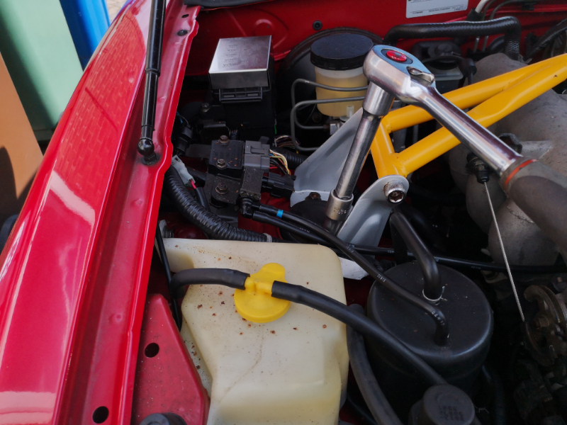
If you have an engine strut brace fitted, you will need it out of the way regardless. So get your 1/2 " drive ratchet ,extensions and 14 mm socket and crack and remove the 2 x 14 mm nuts ( 2 each side) that the strut is secured in place with from the suspension top mounts and put them safe. Remove the strut brace and put in a safe place...

IMG_20190413_125138.jpg
IMG_20190413_125138.jpg (535.4 KiB) Viewed 4289 times


IMG_20190413_125259.jpg
IMG_20190413_125259.jpg (440.24 KiB) Viewed 4289 times


IMG_20190413_125306.jpg
IMG_20190413_125306.jpg (540.51 KiB) Viewed 4289 times


Now we can remove the air box ( I prefer it out of the way, but it is down to personal choice) .....

First we need to open up the cable clip for the AFM plug, by way of a small flat driver etc to push the lock tap back and release it by pulling up the other half, use the same small driver to push the spring loaded holding wire on the AFM plug one side at a time ( it does not need a lot of force), push and pull the plug and then the same on the other side to remove the plug.....

IMG_20190413_124642.jpg
IMG_20190413_124642.jpg (461.09 KiB) Viewed 4289 times


IMG_20190413_124655.jpg
IMG_20190413_124655.jpg (459.41 KiB) Viewed 4289 times


IMG_20190413_124719.jpg
IMG_20190413_124719.jpg (509.85 KiB) Viewed 4289 times


IMG_20190418_172801.jpg
IMG_20190418_172801.jpg (558.72 KiB) Viewed 4290 times


IMG_20190418_173004.jpg
IMG_20190418_173004.jpg (501.96 KiB) Viewed 4290 times


IMG_20190418_173013.jpg
IMG_20190418_173013.jpg (461.63 KiB) Viewed 4290 times


IMG_20190418_173028.jpg
IMG_20190418_173028.jpg (514.25 KiB) Viewed 4290 times


IMG_20190418_173046.jpg
IMG_20190418_173046.jpg (531.86 KiB) Viewed 4290 times


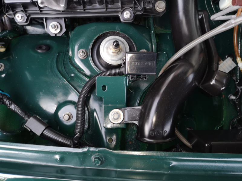
Then we need to undo all the holding bolts...10 mm first that holds the snorkel and diagnostic bracket in place...

IMG_20190418_173123.jpg
IMG_20190418_173123.jpg (501.29 KiB) Viewed 4290 times


IMG_20190418_173126.jpg
IMG_20190418_173126.jpg (536.62 KiB) Viewed 4290 times


IMG_20190418_173134.jpg
IMG_20190418_173134.jpg (493.48 KiB) Viewed 4290 times


IMG_20190418_173151.jpg
IMG_20190418_173151.jpg (470.82 KiB) Viewed 4290 times


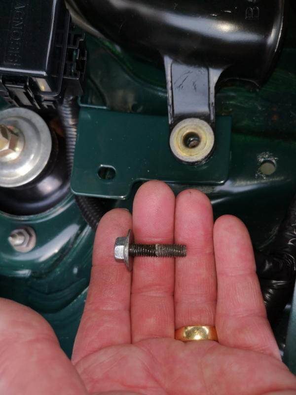
And the the two 12 mm bolts front and back and 12 mm nut ....

IMG_20190418_173206.jpg
IMG_20190418_173206.jpg (420.72 KiB) Viewed 4290 times


IMG_20190418_173214.jpg
IMG_20190418_173214.jpg (435.84 KiB) Viewed 4290 times


IMG_20190418_173251.jpg
IMG_20190418_173251.jpg (436.77 KiB) Viewed 4290 times


IMG_20190418_173341.jpg
IMG_20190418_173341.jpg (454.28 KiB) Viewed 4290 times


IMG_20190418_173403.jpg
IMG_20190418_173403.jpg (456.02 KiB) Viewed 4290 times


IMG_20190418_173451.jpg
IMG_20190418_173451.jpg (467.46 KiB) Viewed 4290 times


IMG_20190418_173259.jpg
IMG_20190418_173259.jpg (443.28 KiB) Viewed 4290 times


IMG_20190418_173313.jpg
IMG_20190418_173313.jpg (530.85 KiB) Viewed 4290 times


IMG_20190418_173331.jpg
IMG_20190418_173331.jpg (482.21 KiB) Viewed 4290 times


And then just lift it free and clear for better room for attack....

IMG_20190418_173513.jpg
IMG_20190418_173513.jpg (494.31 KiB) Viewed 4290 times


IMG_20190418_173521.jpg
IMG_20190418_173521.jpg (556.99 KiB) Viewed 4290 times


IMG_20190418_173532.jpg
IMG_20190418_173532.jpg (569.78 KiB) Viewed 4290 times


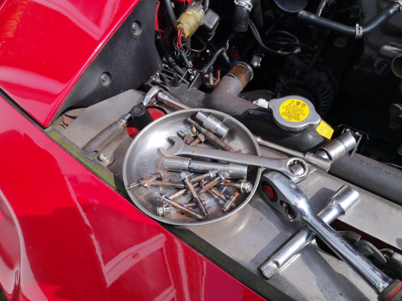
Position a couple of small containers in the bay for nuts and bolts etc to be stored in. We are using magnetic trays from lots of places, even Aldi have them on for sale cheap some times, but a freeing up old oil lids (Plus Gas etc.) will do the job just as well...

IMG_20190413_120723.jpg
IMG_20190413_120723.jpg (562.17 KiB) Viewed 4294 times


IMG_20190413_120727.jpg
IMG_20190413_120727.jpg (583.27 KiB) Viewed 4294 times


Now we need to crack all 3 x 10 mm head water pump pulley bolts and the 4 x 10 mm head crank bolts. This is easier done now while the pulleys are under tension still from the AUX belts, but DO NOT remove the bolts yet. Grab your 1/4 drive ratchet, extension and socket again, the pulley will rotate until the engine brake kicks in to crack them. If the pulley wheel rotates and the Aux belt sits still, you will need to apply more tension onto the belt with the belt adjuster to stop it spinning....

IMG_20190413_120943.jpg
IMG_20190413_120943.jpg (407.54 KiB) Viewed 4292 times


IMG_20190413_121044.jpg
IMG_20190413_121044.jpg (343.79 KiB) Viewed 4292 times


Now we move to the 4 x 10 mm head bolts on the crank pulley ( this needs to be done to all versions at this stage regardless). You will need the 3/8 ratchet and 10 mm socket, you may need to add a small extension to give you clearance because the last thing you want is to round off those 10 mm crank bolts. If you find it easier to use a 1/2 drive to crack them or a breaker bar, all well and good. DO NOT remove them at the minute, we are just loosing them while they are under tension, some as above with the natural engine brake ....

IMG_20190413_121246.jpg
IMG_20190413_121246.jpg (508.59 KiB) Viewed 4292 times


IMG_20190413_121251.jpg
IMG_20190413_121251.jpg (370.87 KiB) Viewed 4292 times


IMG_20190413_121342.jpg
IMG_20190413_121342.jpg (448.69 KiB) Viewed 4292 times


IMG_20190413_121349.jpg
IMG_20190413_121349.jpg (576.38 KiB) Viewed 4292 times


Now we move onto removing the Aux belts, the power steering and A/C Aux belt ( if fitted) sits in front of the alternator/water pump belt on the crank pulley... so power steering or A/C first(if fitted)....

You will need a 1/2 drive ratchet, extension and socket first...and crack the adjuster bolt to the block...

IMG_20190413_123056.jpg
IMG_20190413_123056.jpg (485.39 KiB) Viewed 4292 times


Then the 14 mm hinge bolt and nut, which in most cases ends up behind the pulley wheel, so get a 1/2 drive ratchet and 21 mm socket and turn the crank bolt until it as rotated enough for one of the cut outs to bring the bolt head in view to be able to undo it...

IMG_20190413_123113.jpg
IMG_20190413_123113.jpg (491.29 KiB) Viewed 4292 times


IMG_20190413_123139.jpg
IMG_20190413_123139.jpg (525.11 KiB) Viewed 4292 times


IMG_20190413_123157.jpg
IMG_20190413_123157.jpg (538.46 KiB) Viewed 4292 times


IMG_20190413_123218.jpg
IMG_20190413_123218.jpg (504.26 KiB) Viewed 4292 times


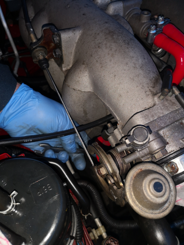
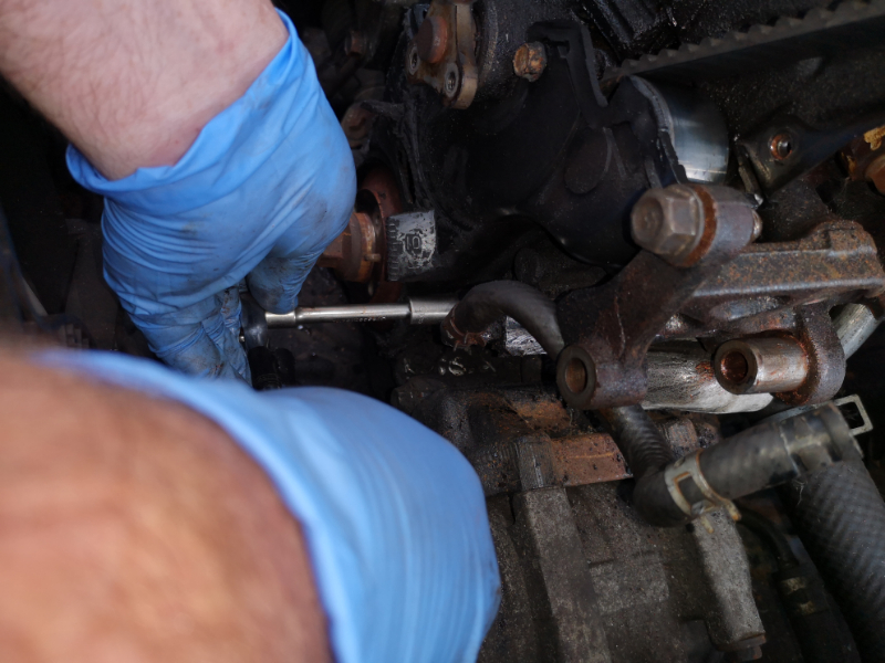
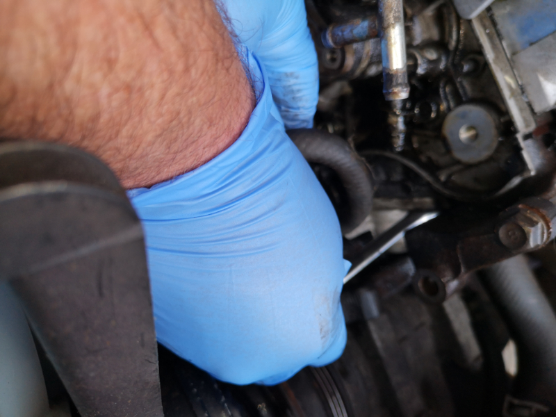
Get your 1/2 drive extension and 14 mm socket on the front of the power steering hinge bolt through the pulley wheel and a 14 mm spanner on the nut at the back and crack it loose.....

IMG_20190413_123256.jpg
IMG_20190413_123256.jpg (456.51 KiB) Viewed 4292 times


Now get your 3/8 drive with a 12 mm socket and 12 mm ring spanner and crack the adjuster locking block bolt loose ...

IMG_20190413_123327.jpg
IMG_20190413_123327.jpg (472.92 KiB) Viewed 4292 times


Then you can wind the tension off the belt with the 12mm...

IMG_20190413_123344.jpg
IMG_20190413_123344.jpg (451.82 KiB) Viewed 4292 times


IMG_20190413_123413.jpg
IMG_20190413_123413.jpg (502.17 KiB) Viewed 4292 times


Press it down and re move the Aux belt.....

IMG_20190413_123422.jpg
IMG_20190413_123422.jpg (479.6 KiB) Viewed 4292 times


IMG_20190413_123433.jpg
IMG_20190413_123433.jpg (562.08 KiB) Viewed 4292 times


Now onto the alternator....

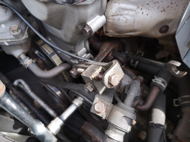
Hinge bolt first. Grab your 1/2 drive with an extension, 14 mm socket and 14 mm ring spanner has a bolt and nut which is fed from the front to the back, and are far easier to remove and undo and does not seize like the later versions.

So ring spanner on the back and ratchet at the front and undo/loosen the bolt MK 1 1.6, either or just on the back for the later versions and crack it loose. Please be careful as it is tight down there, have your swear jar handy for the later roadsters...


IMG_20190413_122736.jpg
IMG_20190413_122736.jpg (531.04 KiB) Viewed 4292 times


IMG_20190413_122742.jpg
IMG_20190413_122742.jpg (467.56 KiB) Viewed 4292 times


IMG_20190413_122813.jpg
IMG_20190413_122813.jpg (370.5 KiB) Viewed 4292 times


IMG_20190413_122819.jpg
IMG_20190413_122819.jpg (461.05 KiB) Viewed 4292 times


IMG_20190413_122834.jpg
IMG_20190413_122834.jpg (427.41 KiB) Viewed 4292 times


Once loose onto the adjuster and block which is a 12 mm again On the MK 1 1.6 the locking bolt is fed from the back to the thread in the alternator arm ....

So slacken the 12 mm bolt on the back with a ring spanner on the locking block and wind the adjuster bolt off with a 1/4 drive ratchet and 12 mm socket(there is no need to remove the adjuster bolt and locking block)...

IMG_20190417_201029.jpg
IMG_20190417_201029.jpg (498.85 KiB) Viewed 4291 times


IMG_20190417_201039.jpg
IMG_20190417_201039.jpg (544.71 KiB) Viewed 4291 times


IMG_20190417_201118.jpg
IMG_20190417_201118.jpg (382.2 KiB) Viewed 4291 times


IMG_20190417_201133.jpg
IMG_20190417_201133.jpg (452.71 KiB) Viewed 4291 times


IMG_20190417_201219.jpg
IMG_20190417_201219.jpg (485.64 KiB) Viewed 4291 times


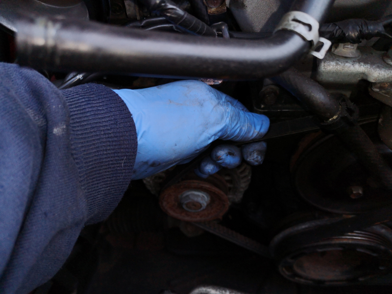
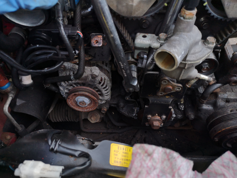
Then just push the alternator towards the engine block to slacken the belt and remove it....

IMG_20190413_123025.jpg
IMG_20190413_123025.jpg (452.71 KiB) Viewed 4291 times


IMG_20190413_123032.jpg
IMG_20190413_123032.jpg (516.87 KiB) Viewed 4291 times


IMG_20190413_123633.jpg
IMG_20190413_123633.jpg (529.77 KiB) Viewed 4291 times


IMG_20190413_123646.jpg
IMG_20190413_123646.jpg (527.54 KiB) Viewed 4291 times


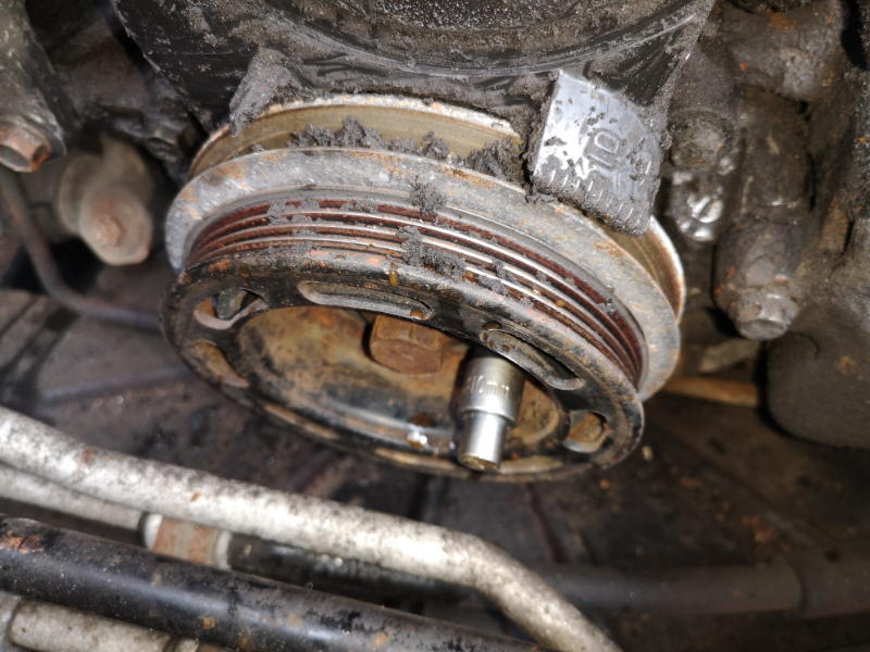
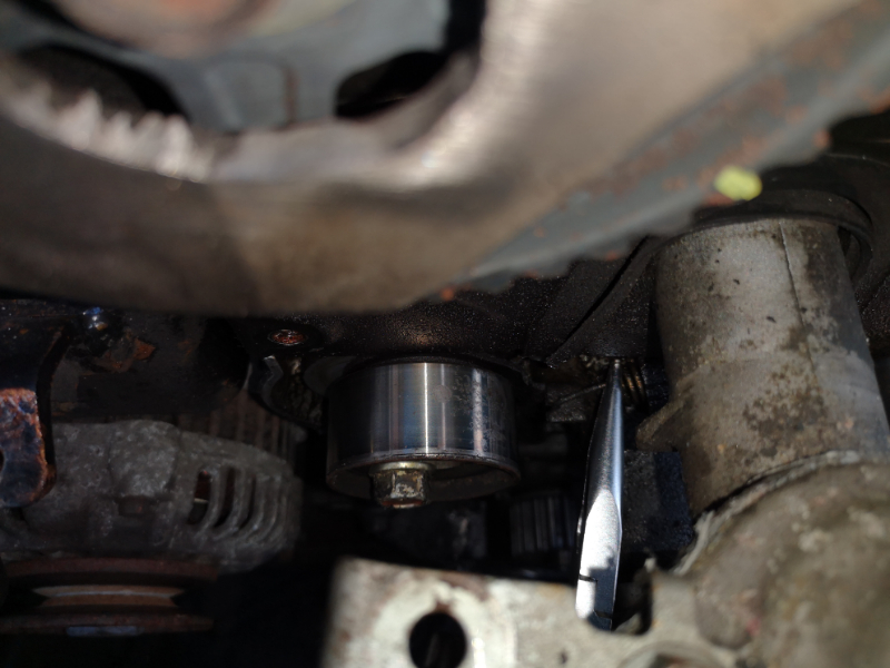
We can now remove the water pump pulley and with cracking the 3 x 10 mm bolts it should be a simple turn out with your fingers...

IMG_20190413_123744.jpg
IMG_20190413_123744.jpg (416.05 KiB) Viewed 4291 times


IMG_20190413_123826.jpg
IMG_20190413_123826.jpg (554.68 KiB) Viewed 4291 times


IMG_20190413_123829.jpg
IMG_20190413_123829.jpg (474.8 KiB) Viewed 4291 times


IMG_20190413_123838.jpg
IMG_20190413_123838.jpg (433.94 KiB) Viewed 4291 times


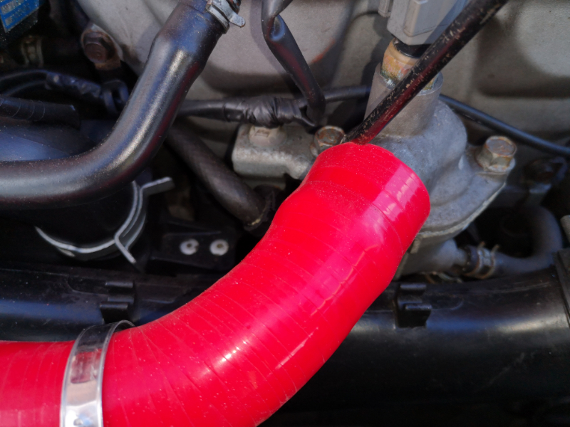
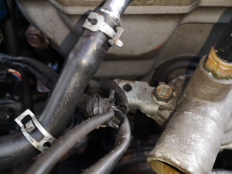
Now move the clips on the hoses on the thermostat housing ready for disconnecting.....

IMG_20190413_124014.jpg
IMG_20190413_124014.jpg (446.34 KiB) Viewed 4291 times


With your chosen hose removal tool, and disconnect the hoses...now be careful with these hoses as they are no the biggest and can be easily damaged....

IMG_20190413_124235.jpg
IMG_20190413_124235.jpg (542.86 KiB) Viewed 4289 times


IMG_20190413_124245.jpg
IMG_20190413_124245.jpg (477.11 KiB) Viewed 4289 times


IMG_20190413_124421.jpg
IMG_20190413_124421.jpg (494.27 KiB) Viewed 4289 times


IMG_20190413_124453.jpg
IMG_20190413_124453.jpg (501.85 KiB) Viewed 4289 times


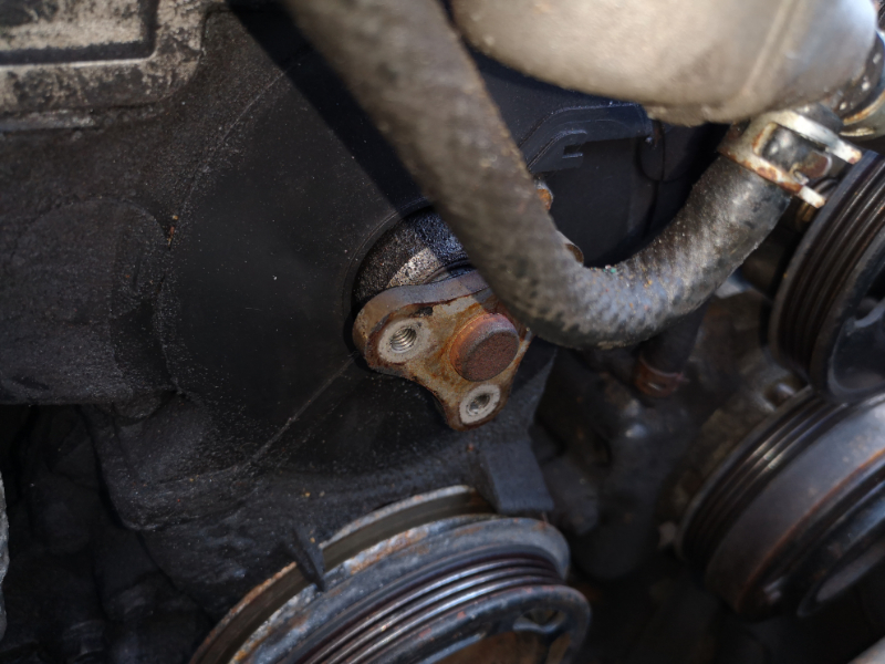
We need to get the power steering pump out of the way while we work (that's if you have it fitted) disconnect the sensor plug from the top of the unit...

IMG_20190413_125757.jpg
IMG_20190413_125757.jpg (529.82 KiB) Viewed 4289 times


IMG_20190413_125805.jpg
IMG_20190413_125805.jpg (409.33 KiB) Viewed 4289 times


Now turn the 14 mm bolt out now that we cracked before and put safe...

IMG_20190413_125439.jpg
IMG_20190413_125439.jpg (497.91 KiB) Viewed 4289 times


IMG_20190413_125524.jpg
IMG_20190413_125524.jpg (490.29 KiB) Viewed 4289 times


Once removed we need to remove the hinge bolt, 14 mm socket through the pulley wheel and spanner on the back and turn from the front with the ratchet while holding the spanner, remove the nut and bolt, and put safe...

IMG_20190413_125622_1_BURST012.jpg
IMG_20190413_125622_1_BURST012.jpg (548.77 KiB) Viewed 4289 times


IMG_20190413_125639.jpg
IMG_20190413_125639.jpg (482.95 KiB) Viewed 4289 times


IMG_20190413_125659.jpg
IMG_20190413_125659.jpg (566.7 KiB) Viewed 4289 times


IMG_20190413_125713.jpg
IMG_20190413_125713.jpg (540.37 KiB) Viewed 4289 times


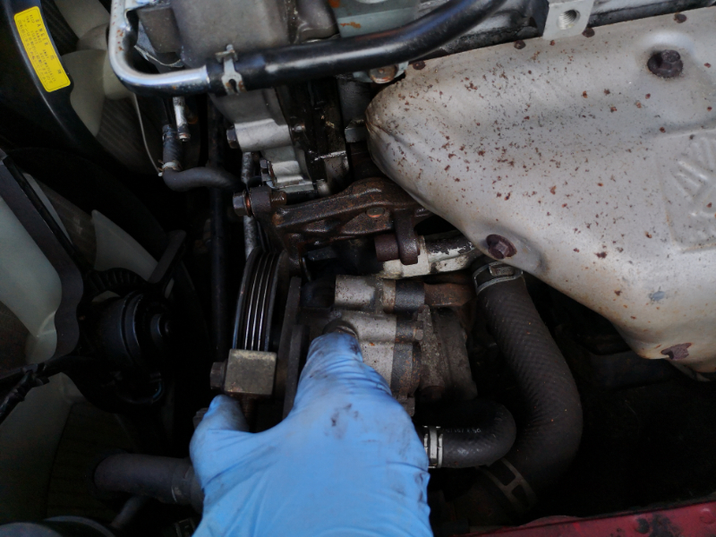
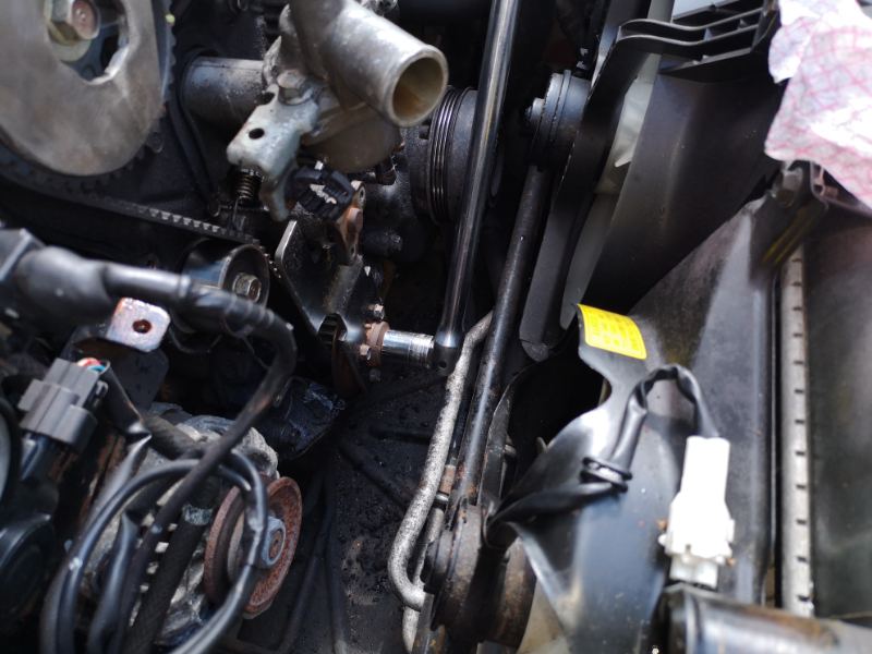
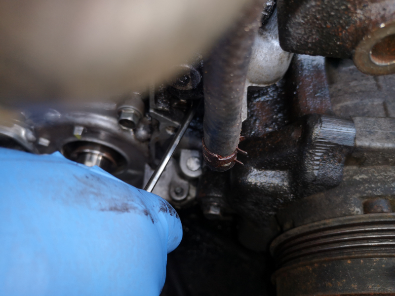
Pull the unit free from the engine mounted bracket ( it may need a pry out with a large flat screw driver) and secure the pump safe and out of the way with a bungee cord etc....

IMG_20190413_125949.jpg
IMG_20190413_125949.jpg (507.88 KiB) Viewed 4289 times


IMG_20190413_130103.jpg
IMG_20190413_130103.jpg (548.8 KiB) Viewed 4289 times


Get a piece of metal bar etc and a lump hammer and give the adjuster spacer a nudge back a couple of mm , this will help on refitting the pump again without a struggle...

IMG_20190413_130357.jpg
IMG_20190413_130357.jpg (749.12 KiB) Viewed 4289 times


IMG_20190413_130432.jpg
IMG_20190413_130432.jpg (516.88 KiB) Viewed 4289 times


IMG_20190413_130425.jpg
IMG_20190413_130425.jpg (512.7 KiB) Viewed 4289 times


IMG_20190413_130447.jpg
IMG_20190413_130447.jpg (491.83 KiB) Viewed 4289 times


Now you can carry on undoing the front loom from the engine and put out of the way...

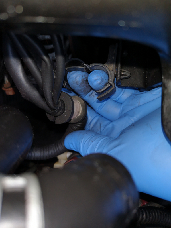
Mk 1 1.6 fan switch on the thermostat cap, press the tab and lift off and free. Be careful as a old sensor can be brittle. If it pulls apart from the body, replace it with a new one. fixing the inner back in is not going to help..

IMG_20190413_125819.jpg
IMG_20190413_125819.jpg (428.85 KiB) Viewed 4289 times


IMG_20190413_125833.jpg
IMG_20190413_125833.jpg (474.49 KiB) Viewed 4289 times


Then release the tab from the bracket off the thermostat cap...

IMG_20190413_125911.jpg
IMG_20190413_125911.jpg (436.39 KiB) Viewed 4289 times


You can unclip more if wish, but put the loom out of the way safe..

Remove the 4 x 10 mm crank pulley bolts, we cracked them earlier so it should be a case of just turning them out with your fingers, remove them and the spacer washer ( if not rusted in place?)and put them safe. We will be needing 4 x 10 mm bolts for bolting up the locking tool later....

IMG_20190413_134226.jpg
IMG_20190413_134226.jpg (553.13 KiB) Viewed 4288 times


IMG_20190413_134339.jpg
IMG_20190413_134339.jpg (496.52 KiB) Viewed 4288 times


Split the pulley from the base. As you can clearly see from the pics, the pulley was catching the engine cover, which means the last person to be in here did not fit everything back correct, so a new cover will be needed...

IMG_20190413_134419.jpg
IMG_20190413_134419.jpg (576.65 KiB) Viewed 4288 times


IMG_20190413_134423.jpg
IMG_20190413_134423.jpg (574.3 KiB) Viewed 4288 times


IMG_20190413_134429.jpg
IMG_20190413_134429.jpg (788.35 KiB) Viewed 4288 times


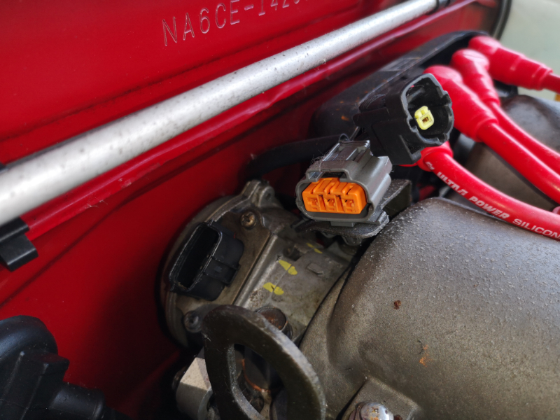
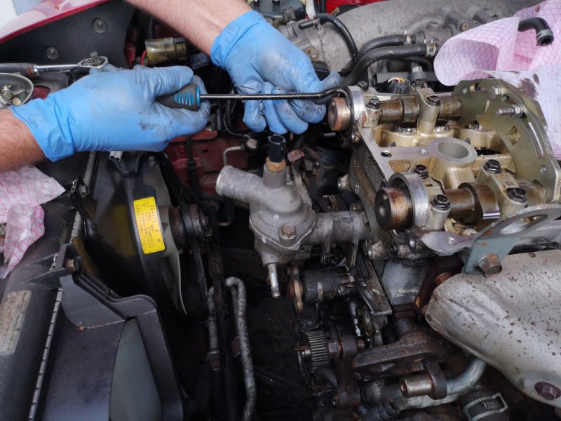
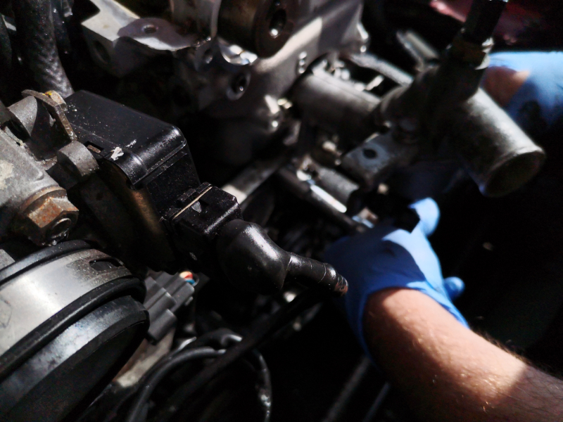
Now onto the coil pack , you can just unbolt and leave the coil pack at the back resting on the fire wall, but we are removing it because of other jobs we need to do...

The Mk 1 1.6 plug cluster, coil pack, CAS and O2/Lamba sensor , unplug them...

IMG_20190413_134453.jpg
IMG_20190413_134453.jpg (506.4 KiB) Viewed 4288 times


IMG_20190413_134501.jpg
IMG_20190413_134501.jpg (487.54 KiB) Viewed 4288 times


IMG_20190413_134542.jpg
IMG_20190413_134542.jpg (467.8 KiB) Viewed 4288 times


IMG_20190413_134558.jpg
IMG_20190413_134558.jpg (499.04 KiB) Viewed 4288 times


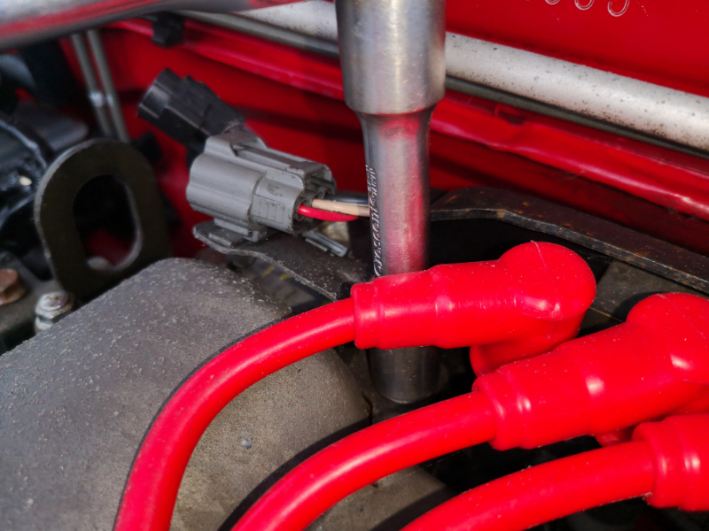
Now get your 12 mm ring spanner and feel down the back and locate the 12 mm bolt that holds the frame to the engine block ( you will love this bolt)once you have sworn a lot, scraped all your knuckles, you will be glad to know that you do not need to replace it on the rebuild....

IMG_20190413_135548.jpg
IMG_20190413_135548.jpg (446.78 KiB) Viewed 4268 times


IMG_20190413_135556.jpg
IMG_20190413_135556.jpg (500.98 KiB) Viewed 4268 times


IMG_20190413_135607.jpg
IMG_20190413_135607.jpg (443.42 KiB) Viewed 4268 times


Get your 3/8 ratchet, extension and 12mm socket and undo and remove the 2 x 12mm bolts that hold the coil pack frame to the rocker cover...

IMG_20190413_134647.jpg
IMG_20190413_134647.jpg (590.74 KiB) Viewed 4268 times


IMG_20190413_134700.jpg
IMG_20190413_134700.jpg (532.43 KiB) Viewed 4268 times


IMG_20190413_134746.jpg
IMG_20190413_134746.jpg (460.91 KiB) Viewed 4268 times


And remove the coil pack and HT leads safely out of the way ....

IMG_20190413_135703.jpg
IMG_20190413_135703.jpg (540.52 KiB) Viewed 4268 times


IMG_20190413_135710.jpg
IMG_20190413_135710.jpg (464.25 KiB) Viewed 4268 times


Disconnect the hose or remove the PCV from the rocker cover....

IMG_20190417_193854.jpg
IMG_20190417_193854.jpg (493.5 KiB) Viewed 4268 times


IMG_20190417_193845.jpg
IMG_20190417_193845.jpg (496.13 KiB) Viewed 4268 times


Now onto removing the rocker cover, get your 1/4 ratchet with an extension and 10 mm socket and undo and remove the 11 x 10 mm head bolts and put them safe....

IMG_20190413_135752.jpg
IMG_20190413_135752.jpg (586.87 KiB) Viewed 4268 times


IMG_20190413_135957.jpg
IMG_20190413_135957.jpg (508.51 KiB) Viewed 4268 times


IMG_20190413_140019.jpg
IMG_20190413_140019.jpg (553.25 KiB) Viewed 4268 times


IMG_20190413_140027.jpg
IMG_20190413_140027.jpg (549.92 KiB) Viewed 4268 times


And just lift the rocker cover off the head of the engine and put somewhere safe, it maybe stuck fast with the old rocker seal holding on for dear life, it will break free as long as all the bolts are removed so don't worry about giving it a little more Grrrrrrr.

IMG_20190413_140218.jpg
IMG_20190413_140218.jpg (563.22 KiB) Viewed 4268 times


IMG_20190413_140449.jpg
IMG_20190413_140449.jpg (632.4 KiB) Viewed 4268 times


Now we can start to remove the front plastic engine covers , with the 1/4 ratchet,extension and 10 mm socket and remove the 4 x 10 mm head bolts from the top most cover taking note of where the two brackets go, one to hold a guide the loom and the other to hold the coolant hose safe from moving and catching the Aux belts/pulley's....


IMG_20190413_140707.jpg
IMG_20190413_140707.jpg (578 KiB) Viewed 4268 times


IMG_20190413_140714.jpg
IMG_20190413_140714.jpg (591.64 KiB) Viewed 4268 times


IMG_20190413_140724.jpg
IMG_20190413_140724.jpg (572.62 KiB) Viewed 4268 times


IMG_20190413_140731.jpg
IMG_20190413_140731.jpg (559.85 KiB) Viewed 4268 times


IMG_20190413_140825.jpg
IMG_20190413_140825.jpg (487.61 KiB) Viewed 4268 times


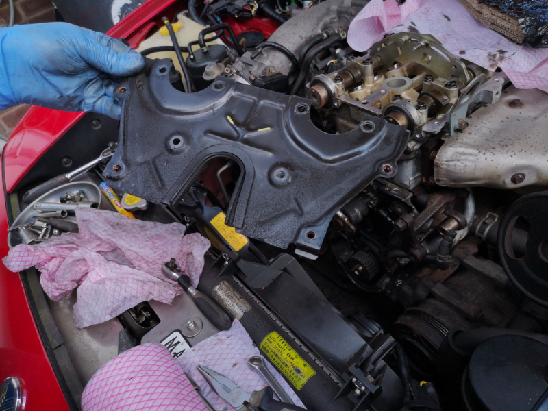
And pull it free from the cam shield back plate and put safe....

IMG_20190413_140833.jpg
IMG_20190413_140833.jpg (574.49 KiB) Viewed 4268 times


Now onto the middle one with is held in place with a 1 x 10 mm head bolt again, so just remove the bolt and cover and put it safe with the other top guard...

IMG_20190413_140933.jpg
IMG_20190413_140933.jpg (490.06 KiB) Viewed 4268 times


IMG_20190413_140952.jpg
IMG_20190413_140952.jpg (505.26 KiB) Viewed 4268 times


And then onto the bottom section which is held in place by 3 x 10 mm head bolts that need removing 1 at the top near the water pump pulley and two at the bottom on either side of the crank, remove all 3 10 mm head bolts and pull the bottom section free and away from the engine and put safe with the other two guards...

IMG_20190413_141029.jpg
IMG_20190413_141029.jpg (491.05 KiB) Viewed 4268 times


IMG_20190413_141052.jpg
IMG_20190413_141052.jpg (433.95 KiB) Viewed 4268 times


IMG_20190413_141102.jpg
IMG_20190413_141102.jpg (415.37 KiB) Viewed 4268 times


IMG_20190413_141114.jpg
IMG_20190413_141114.jpg (457.71 KiB) Viewed 4268 times


IMG_20190413_141132.jpg
IMG_20190413_141132.jpg (411.73 KiB) Viewed 4268 times


IMG_20190413_141138.jpg
IMG_20190413_141138.jpg (429.6 KiB) Viewed 4268 times


IMG_20190413_141209.jpg
IMG_20190413_141209.jpg (521.99 KiB) Viewed 4268 times


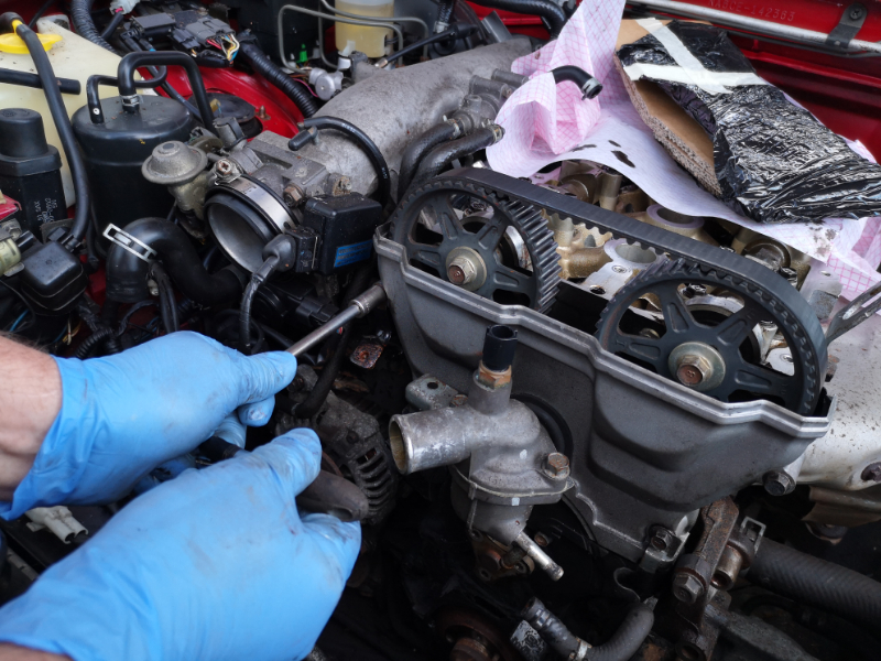
Now get your 1/2" drive ratchet and a 21 mm socket and put it onto the crank bolt and turn it until you have "ALL" the timing marks in the correct place, crank and cams and mark them up so you cannot miss them...

IMG_20190413_141317.jpg
IMG_20190413_141317.jpg (419.82 KiB) Viewed 4266 times


IMG_20190413_141355.jpg
IMG_20190413_141355.jpg (544.34 KiB) Viewed 4266 times


IMG_20190413_141400.jpg
IMG_20190413_141400.jpg (478.01 KiB) Viewed 4266 times


IMG_20190413_141413.jpg
IMG_20190413_141413.jpg (479.27 KiB) Viewed 4266 times


There is an E and a I on the back plate with a raised Y section which is the line up mark and cam pulley's which need to be lined up correct with the E and I also to match the back plate there is a small cut out line on the teeth edge of the pulley's , that is our line up mark ...

IMG_20190211_113756.jpg
IMG_20190211_113756.jpg (548.34 KiB) Viewed 4238 times


WE have locked up the cam shafts on the cast 26 mm or 23 mm nut with the Jass Performance locking tool, which is locked up with the 10 mm head nuts and bolts that come with the tool....


IMG_20190413_142602.jpg
IMG_20190413_142602.jpg (613.34 KiB) Viewed 4266 times


***LINK TO GUIDE on how to use****
----------------------------------------------------------------------------------------------------------------------------
SNC (Short Nose Crank) PLEASE NOTE

Once the pulley is removed there is no need to add a locking tool and remove the crank bolt to change the timing belt, if the crank shaft seal is weeping oil than the bolt and crank cog and woodruff key will need to be removed to remove the old seal and fit a new one, if this as been the case then we highly recommend that you fit a new key and crank bolt with heavy duty thread lock to the correct torqued as mentioned in section one as the SNC and LNC are torqued up at different torque settings (important) and leave the thread lock to go off completely before running the engine.

DSC00733.JPG
DSC00733.JPG (573.17 KiB) Viewed 4215 times


DSC00220.JPG
DSC00220.JPG (517.13 KiB) Viewed 4215 times


DSC00213.JPG
DSC00213.JPG (550.62 KiB) Viewed 4215 times


If you need info or advice on this procedure with a SNC please contact us for help and advice until the info is added.

----------------------------------------------------------------------------------------------------------------------------
Now we attach our crank locking tool, in this case we are using the Junk yard dog locking tool, very simple and easy to use and locks the crank up at top dead, so you re use the 4 x 10 mm head bolts that held the pulley wheel in place

IMG_20190413_141439.jpg
IMG_20190413_141439.jpg (590.42 KiB) Viewed 4266 times


IMG_20190413_141656.jpg
IMG_20190413_141656.jpg (603.54 KiB) Viewed 4266 times


IMG_20190413_141816.jpg
IMG_20190413_141816.jpg (536.71 KiB) Viewed 4266 times


IMG_20190413_142555.jpg
IMG_20190413_142555.jpg (503.83 KiB) Viewed 4266 times


****LINK >>>>> viewtopic.php?f=193&t=4016


So once all locked up with all timing marks lined up, get your 1/2" 21 mm socket and large 1/2" breaker bar and crack that crank bolt, no need to remove it for the minute...

IMG_20190413_142632.jpg
IMG_20190413_142632.jpg (475.08 KiB) Viewed 4265 times


Now crack the tensioner and idler bolts with a 1/2" 14 mm socket, and we used a medium size 1/2" breaker bar, do not remove them yet...

IMG_20190413_142706.jpg
IMG_20190413_142706.jpg (469.42 KiB) Viewed 4265 times


IMG_20190413_142720.jpg
IMG_20190413_142720.jpg (528.03 KiB) Viewed 4265 times


Now with the handle of the larger breaker bar etc, push the tensioner outwards and re tighten the 14 mm locking bolt.....

IMG_20190413_142759.jpg
IMG_20190413_142759.jpg (504.81 KiB) Viewed 4265 times


IMG_20190413_142809.jpg
IMG_20190413_142809.jpg (513.47 KiB) Viewed 4265 times


Now screw out the 21 mm crank bolt and remove the locking tool and crank boss....

IMG_20190413_142827.jpg
IMG_20190413_142827.jpg (525.3 KiB) Viewed 4265 times


IMG_20190413_142843.jpg
IMG_20190413_142843.jpg (560.33 KiB) Viewed 4265 times


IMG_20190413_142853.jpg
IMG_20190413_142853.jpg (607.58 KiB) Viewed 4265 times


And remove the timing belt.....

IMG_20190413_142904.jpg
IMG_20190413_142904.jpg (594.18 KiB) Viewed 4265 times


Undo the 14 mm head locking bolt for the tensioner so it pulls back ob the tension spring....

IMG_20190413_142921.jpg
IMG_20190413_142921.jpg (485.27 KiB) Viewed 4265 times


IMG_20190413_142934.jpg
IMG_20190413_142934.jpg (547.92 KiB) Viewed 4265 times


Get your pointed long nose pliers and remove the tension spring...

IMG_20190413_142943.jpg
IMG_20190413_142943.jpg (460.22 KiB) Viewed 4265 times


IMG_20190413_143005.jpg
IMG_20190413_143005.jpg (381.42 KiB) Viewed 4265 times


IMG_20190413_143014.jpg
IMG_20190413_143014.jpg (458.98 KiB) Viewed 4265 times


IMG_20190413_143020.jpg
IMG_20190413_143020.jpg (569.93 KiB) Viewed 4265 times


Now remove both 14 mm locking bolts from the tensioner and idler and remove the tension and idler, taking note of which bolt went with which bearing roller and put safe for re use....

IMG_20190413_143041.jpg
IMG_20190413_143041.jpg (494.75 KiB) Viewed 4265 times


IMG_20190413_143048.jpg
IMG_20190413_143048.jpg (489.17 KiB) Viewed 4265 times


IMG_20190413_143059.jpg
IMG_20190413_143059.jpg (479.15 KiB) Viewed 4265 times


****Now you only need to follow this bit if you are changing the cam seals, we highly recommend that you do as it is of a age related importance, and you have gone this far so seems a no brainer not to really****

Now crack and remove the 14mm head bolts that hold the cam wheels in place, with a 14 mm 1/2" socket and medium breaker bar, and remove the cam wheels leaving them safe somewhere ready to be re installed in the correct way as removed later( we were pre testing another prototype cam wheel locking tool in this guide)...

IMG_20190413_143136.jpg
IMG_20190413_143136.jpg (582.81 KiB) Viewed 4264 times


IMG_20190413_143142.jpg
IMG_20190413_143142.jpg (541.61 KiB) Viewed 4264 times


IMG_20190413_143206.jpg
IMG_20190413_143206.jpg (568 KiB) Viewed 4264 times


IMG_20190413_143219.jpg
IMG_20190413_143219.jpg (561.87 KiB) Viewed 4264 times


IMG_20190413_143246.jpg
IMG_20190413_143246.jpg (596.77 KiB) Viewed 4264 times


IMG_20190413_143256.jpg
IMG_20190413_143256.jpg (584.31 KiB) Viewed 4264 times


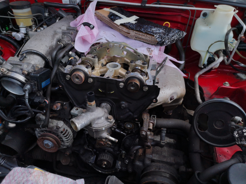
Now get your 1/4 drive ratchet ,extension bar and 10 mm socket and remove the 6 x 10 mm head bolts that hold the back plate in place, put the bolts safe and remove the back plate, as you can clearly see the cam seal were leaking and did need refreshing...

IMG_20190413_143330.jpg
IMG_20190413_143330.jpg (570.77 KiB) Viewed 4264 times


IMG_20190413_143337.jpg
IMG_20190413_143337.jpg (566.45 KiB) Viewed 4264 times


IMG_20190413_143340.jpg
IMG_20190413_143340.jpg (591.17 KiB) Viewed 4264 times


IMG_20190413_143343.jpg
IMG_20190413_143343.jpg (585 KiB) Viewed 4264 times


IMG_20190413_143348.jpg
IMG_20190413_143348.jpg (532.85 KiB) Viewed 4264 times


IMG_20190413_143357.jpg
IMG_20190413_143357.jpg (563.08 KiB) Viewed 4264 times


IMG_20190413_143407.jpg
IMG_20190413_143407.jpg (577.68 KiB) Viewed 4264 times


IMG_20190413_143453.jpg
IMG_20190413_143453.jpg (536.12 KiB) Viewed 4264 times


IMG_20190413_143457.jpg
IMG_20190413_143457.jpg (503.41 KiB) Viewed 4264 times


IMG_20190413_143504.jpg
IMG_20190413_143504.jpg (610.21 KiB) Viewed 4264 times


IMG_20190413_143511.jpg
IMG_20190413_143511.jpg (587.88 KiB) Viewed 4264 times


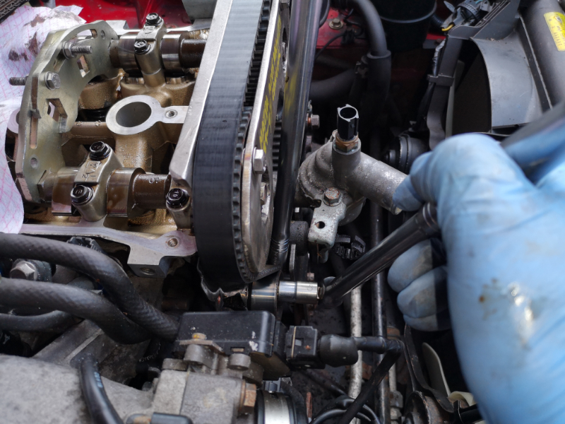
Now get your tool of choice to remove the seals, if you use a hook, please make sure you only connect with the seal for removal, DO NOT scrap the shaft or cam walls as it will mean the new seal....will not seal correct, some screw in a self tapper to the seal and then pull it out,some undo the top arch from the head and remove it that way, just make sure you add fresh sealant to the corners, do it which ever way works for you just do not damage the walls, with the hook it is a case of just hooking in through the bottom where it meets the cam shaft and levering it out, it might take a couple of tries as most of the time they are dry and the rubber is brittle and just snaps, so just take your time.

IMG_20190413_143526.jpg
IMG_20190413_143526.jpg (611.94 KiB) Viewed 4264 times


IMG_20190413_143530.jpg
IMG_20190413_143530.jpg (571.56 KiB) Viewed 4264 times


IMG_20190413_143541.jpg
IMG_20190413_143541.jpg (588.7 KiB) Viewed 4264 times


IMG_20190413_143548.jpg
IMG_20190413_143548.jpg (611.21 KiB) Viewed 4264 times


IMG_20190413_143551.jpg
IMG_20190413_143551.jpg (511.85 KiB) Viewed 4264 times


IMG_20190413_143600.jpg
IMG_20190413_143600.jpg (539.98 KiB) Viewed 4264 times


IMG_20190413_143604.jpg
IMG_20190413_143604.jpg (580.69 KiB) Viewed 4264 times


IMG_20190413_143629.jpg
IMG_20190413_143629.jpg (575.78 KiB) Viewed 4264 times


IMG_20190413_143640.jpg
IMG_20190413_143640.jpg (512 KiB) Viewed 4264 times


IMG_20190413_143649.jpg
IMG_20190413_143649.jpg (599.26 KiB) Viewed 4264 times


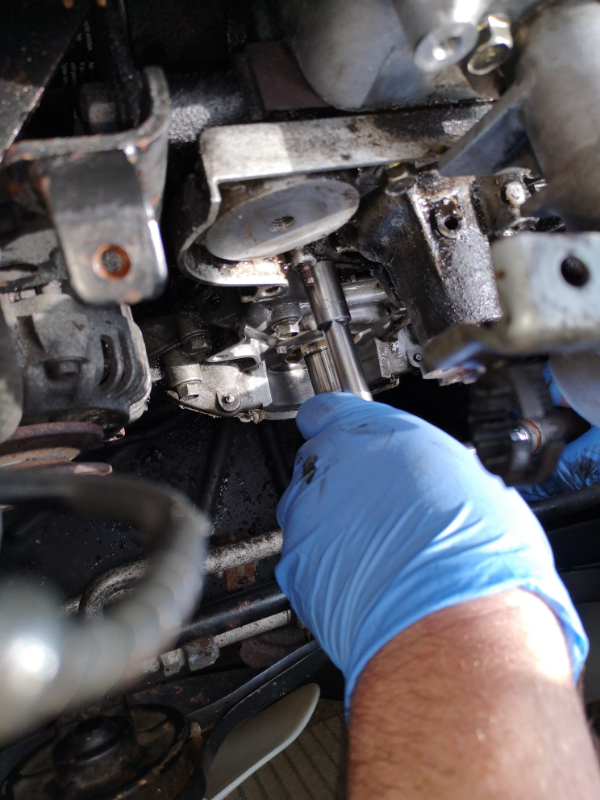
Now remove the crank cog and wood-ruff key, some can put up a fight and it does not take much surface rust to hold on good and tight. If so spray with a penetrating oil and pry at the back, once you have it moving forward even if it just a little, that's fine ,DO NOT RUSH IT, DO NOT OVER FORCE IT, it will snap very easy, so it has moved forward, spray the back again and tap back ,and pry, spray and tap until it works its way off, IF you can get the wood ruff key out even better as you can spray and rotate the cog on the crank shaft to get movement, trust me all the guys that work on these have at some point smashed a crank cog to bits from to much force and rushing, most of the time its fine but you do hit that fighter every now and then....

This one gave a little fight but nothing major....

IMG_20190413_143705.jpg
IMG_20190413_143705.jpg (508.18 KiB) Viewed 4264 times


IMG_20190413_143709.jpg
IMG_20190413_143709.jpg (494.62 KiB) Viewed 4264 times


IMG_20190413_143719.jpg
IMG_20190413_143719.jpg (479.45 KiB) Viewed 4264 times


IMG_20190413_143728.jpg
IMG_20190413_143728.jpg (532.06 KiB) Viewed 4264 times

--------------------------------------------------------------------------------------------------------------------------------------------------------

MK 1 1.6 SNC....


If you need info or advice on this procedure with a SNC please contact us for help and advice until the info is added.

--------------------------------------------------------------------------------------------------------------------------------------------------------


So once removed clean up the top where the oil as weep from the dry cam seals and clean up the area around the crank seal if you are replacing, a can of freeing up oil is perfect for breaking the old oil down and just wipe with some old rags...


IMG_20190413_150041.jpg
IMG_20190413_150041.jpg (571.06 KiB) Viewed 4264 times


IMG_20190413_150045.jpg
IMG_20190413_150045.jpg (526.14 KiB) Viewed 4264 times


Remove the crank seal in the same way you removed the cam seals, making sure you do not damage the crank shaft of walls in the process...

IMG_20190413_150057.jpg
IMG_20190413_150057.jpg (497.33 KiB) Viewed 4264 times


IMG_20190413_150106.jpg
IMG_20190413_150106.jpg (468.19 KiB) Viewed 4264 times


IMG_20190413_150111.jpg
IMG_20190413_150111.jpg (525.3 KiB) Viewed 4264 times


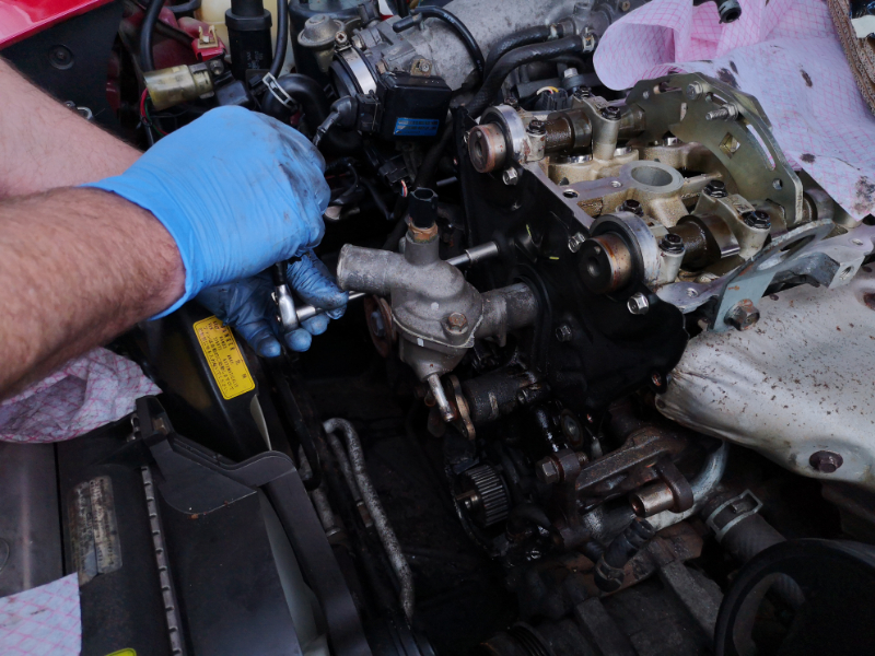
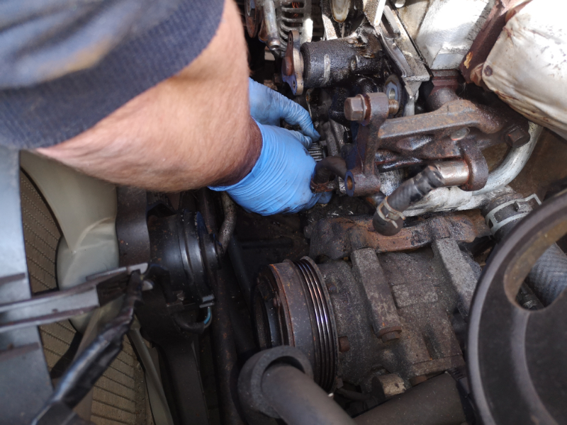
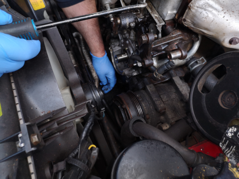
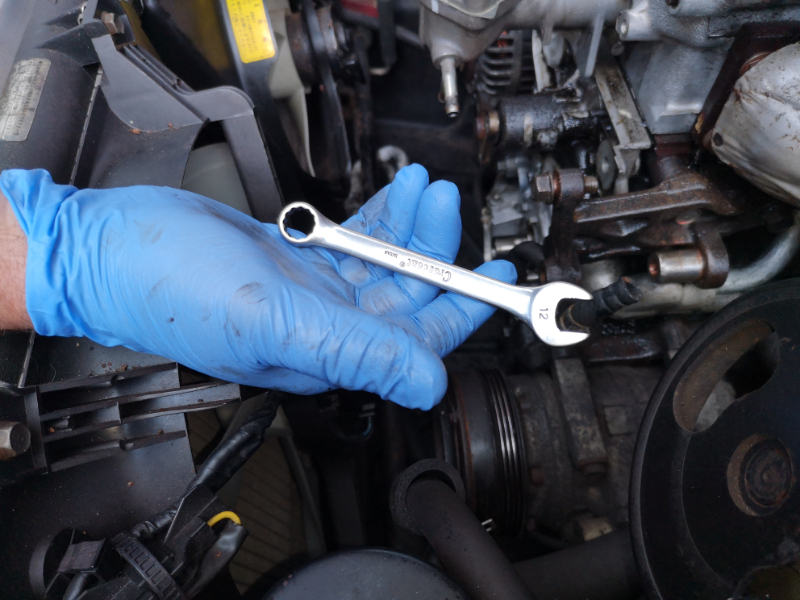
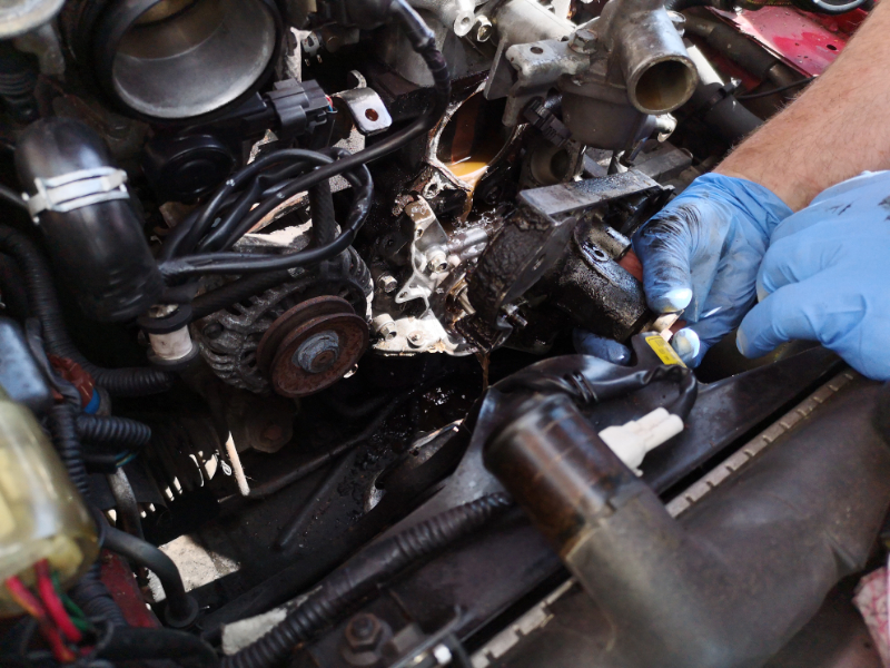
Now get your 12 mm ring spanner and crack and remove the two 12 mm head bolts that hold the water pump inlet to the pump body, if it is and import and as A/C you will find that once the bolts have been cracked a ratchet spanner will help in the tight area if you have one handy.

IMG_20190413_150250.jpg
IMG_20190413_150250.jpg (502.48 KiB) Viewed 4264 times


IMG_20190413_150306.jpg
IMG_20190413_150306.jpg (487.88 KiB) Viewed 4264 times


IMG_20190413_150317.jpg
IMG_20190413_150317.jpg (421.28 KiB) Viewed 4264 times


IMG_20190413_150339.jpg
IMG_20190413_150339.jpg (419.94 KiB) Viewed 4264 times


IMG_20190413_150601.jpg
IMG_20190413_150601.jpg (489.28 KiB) Viewed 4264 times


Now get your 3/8 ratchet, extension bar and 12 mm socket and crack the 4 x 12 mm head bolts that hold the pump to the block ,remove them and put safe and remove the water pump....

IMG_20190413_150729.jpg
IMG_20190413_150729.jpg (502.97 KiB) Viewed 4264 times


IMG_20190413_150738.jpg
IMG_20190413_150738.jpg (475.41 KiB) Viewed 4264 times


IMG_20190413_150750.jpg
IMG_20190413_150750.jpg (508.62 KiB) Viewed 4264 times


IMG_20190413_150758.jpg
IMG_20190413_150758.jpg (501.02 KiB) Viewed 4264 times


IMG_20190413_150832.jpg
IMG_20190413_150832.jpg (454.26 KiB) Viewed 4264 times


IMG_20190413_150841.jpg
IMG_20190413_150841.jpg (574.5 KiB) Viewed 4264 times


IMG_20190413_150848.jpg
IMG_20190413_150848.jpg (643.78 KiB) Viewed 4264 times


IMG_20190413_150855.jpg
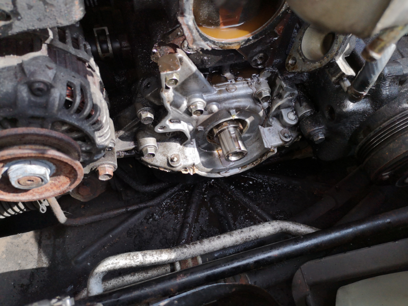
IMG_20190413_150855.jpg (567.15 KiB) Viewed 4264 times


Now before we fit the pump you must make sure that the old gaskets have been removed from the engine block and the face of the water pump inlet, block the inlet and water pump hole if need be with some clean rags to stop the bits of old gasket falling into the water ways, don't use a screw driver for this and gouge the faces, they need to be clean and smooth for the new gaskets to seal correct, you can get gasket scrappers for the job from the likes of Machine Mart etc cheap enough..

We highly recommend that you flush the old coolant out at this stage, regardless of what you are re adding and dry everything down ready for rebuild....

And that's it all stripped down ...on to section 3 and building back up again..

If you have found this guide to be useful, helpful or as helped you with your roadster with saving on garage costs , please consider making a donation to keep these gates available for others and so new info can still be added to carry on helping.

M-m
The Disclaimer:-
This post is a natural product made from recycled electrons. The slight variations in spelling and grammar enhance its individual character and beauty and in no way are to be considered flaws or defects, the articles/answers/comments are provided for information purposes and they are not intended to substitute informed professional advice, I or mazdamenders.net cannot personally be hold responsible for any damage occurred from following this procedure or any injuries from it. Proceed at your own risk.


Mk 1 Eunos 93 black V.S II 1.8 ,
Mk 2 .1/4 Roadster 99 black & gold V.S 1.8 .
Mk 1 Eunos 90 1.6 soul red ..f/ build
MK 2.1/4 Blue V.S Roadster 1.8 99 ..
MK1 1.8 ,white import.. (Ashleighs)
MK1 1.6 yellow J ltd import.f/build
MK 1 1.8 black Tokyo Ltd..f/build


http://www.mx5oc.co.uk/ http://www.mx5nutz.com/forum/ http://miata.net/ http://www.autolinkuk.co.uk/
User avatar
Mazda Mender
Site Admin
Posts: 15090
Joined: Tue Dec 06, 2011 6:18 pm
Location: Pie land, in the glen of Wiganshire
Contact:

Re: MK 1 NA 1.6 SNC/LNC water pump/cam belt change/cam/crank seals etc

Postby Mazda Mender » Wed Aug 07, 2019 7:59 am

******SECTION 3....RE BUILDING BACK UP*****

*****Clicking on the images will enlarge for better viewing*******

Torque settings PDF for download if needed >>>>>>>
Torque (6).pdf
(34.03 KiB) Downloaded 229 times


So get all your new service items together ready for install....

IMG_20190413_152543.jpg
IMG_20190413_152543.jpg (685.65 KiB) Viewed 4264 times


IMG_20190413_152548.jpg
IMG_20190413_152548.jpg (562.03 KiB) Viewed 4264 times


IMG_20190413_152552.jpg
IMG_20190413_152552.jpg (613.16 KiB) Viewed 4264 times


IMG_20190413_152557.jpg
IMG_20190413_152557.jpg (595.6 KiB) Viewed 4264 times

_---------------------------------------------------------------------------------------------------------------------------------

Mk 1 SNC....

To be added...

Please contact if info and advice is needed

-----------------------------------------------------------------------------------------------------------------------------------

Clean and dry the area for the new crank seal, a small spray of silicon lube on the crank shaft can help with the fitting of a new seal, the seal tool we are using is the Jass Performance crank seal tool which a 2 piece insertion tool ****link >>>>>>>> https://www.youtube.com/watch?v=6a34UQFBStY&t=32s ....


IMG_20190413_153243.jpg
IMG_20190413_153243.jpg (504.76 KiB) Viewed 4264 times


IMG_20190413_153246.jpg
IMG_20190413_153246.jpg (470.02 KiB) Viewed 4264 times


IMG_20190413_153308.jpg
IMG_20190413_153308.jpg (479.17 KiB) Viewed 4264 times


Using the OE crank bolt and a 21mm spanner, just tighten the crank bolt which will push the tool to insert the new seal, once driven home just undo the OE crank bolt and the two piece tool...


IMG_20190413_153358.jpg
IMG_20190413_153358.jpg (464.34 KiB) Viewed 4264 times


IMG_20190413_153405.jpg
IMG_20190413_153405.jpg (507.65 KiB) Viewed 4264 times


IMG_20190413_153444.jpg
IMG_20190413_153444.jpg (476.07 KiB) Viewed 4264 times


IMG_20190413_153458.jpg
IMG_20190413_153458.jpg (497.75 KiB) Viewed 4264 times


IMG_20190413_153511.jpg
IMG_20190413_153511.jpg (447.34 KiB) Viewed 4264 times


IMG_20190413_153520.jpg
IMG_20190413_153520.jpg (547.07 KiB) Viewed 4264 times


Next onto the the cam seals, the tool for this is from Autolinkmx5....***LINK >>>> https://www.autolinkmx5.com/camshaft-oi ... zWoRZGywBc which also do the one for the cam seal on the MK 2.5 1.8 VVT engine ****link >>>>> https://www.autolinkmx5.com/camshaft-oi ... u1lQi7CdLc , these are cheap enough and takes the guess work out that it is done correct, when fitting the seal to the cam shaft or the crank shaft, you need to make sure that you DO NOT have the inner shaft seal bent back on itself before driving it in place, as this is easy done and seen it many times, the inner lip folds back on itself and has been driven home, it will not make a seal and it will get oil everywhere, so check now, if you have take it back off and re fit now before it is to late and there is no damage to the seal, personally I start from the bottom to fit and work my way around, as with the crank seal a small spray of silicon lube can help with alignment and fitting...

IMG_20190413_153712.jpg
IMG_20190413_153712.jpg (497.92 KiB) Viewed 4261 times


IMG_20190413_153716.jpg
IMG_20190413_153716.jpg (571.46 KiB) Viewed 4261 times


IMG_20190413_153727.jpg
IMG_20190413_153727.jpg (581.08 KiB) Viewed 4261 times


IMG_20190803_121257.jpg
IMG_20190803_121257.jpg (644.56 KiB) Viewed 4261 times


You can also drift them in with the correct size tube or socket and a small hammer and little taps to insert and it ***MUST END UP STRAIGHT*** and correctly seated....

IMG_20190413_153735.jpg
IMG_20190413_153735.jpg (520.52 KiB) Viewed 4261 times


IMG_20190413_153814.jpg
IMG_20190413_153814.jpg (579.28 KiB) Viewed 4261 times


IMG_20190413_153824.jpg
IMG_20190413_153824.jpg (592.97 KiB) Viewed 4261 times


IMG_20190413_153903.jpg
IMG_20190413_153903.jpg (576.61 KiB) Viewed 4261 times


IMG_20190413_153908.jpg
IMG_20190413_153908.jpg (567.09 KiB) Viewed 4261 times


Pull and twist off the water pump inlet from the pipe and o'ring, it will be dry and give you a fight but it will work loose and pull apart, remove the old rubber o'ring seal and fit the new one, coat it with some red rubber grease before re fitting into the water pump inlet, check the water pump inlet for any oxidizing where the new o'ring and pipe re-fit , it there is a lot? clean it with a little wet and dry, then clean it with some brake cleaner and wipe down , also take the opportunity to check the condition of the L piece hose fitting for rust and the T piece on the thermostat housing as the body is alloy and the L and T pieces are metal ...yep great design fault there Mazda, big thanks.... as they are also not cheap to replace, and once clean push back onto the pipe with the o'ring seal...

MX-5-Waterpump inlet.jpg
MX-5-Waterpump inlet.jpg (400.04 KiB) Viewed 4236 times


jTlRylU0qzMgGbFjwibW4AusLXnq6BEZEvtzYPIa1JA.jpg
jTlRylU0qzMgGbFjwibW4AusLXnq6BEZEvtzYPIa1JA.jpg (350.42 KiB) Viewed 4236 times


pipe-heater-to-waterpump-bypass-mx-5-1.6-mk1-b61p15290b-used-4005-p.jpg
pipe-heater-to-waterpump-bypass-mx-5-1.6-mk1-b61p15290b-used-4005-p.jpg (482.24 KiB) Viewed 4236 times


s-l640.jpg
s-l640.jpg (17.95 KiB) Viewed 4236 times


IMG_20191116_143353.jpg
IMG_20191116_143353.jpg (449.87 KiB) Viewed 4217 times


IMG_20191116_143410.jpg
IMG_20191116_143410.jpg (342.63 KiB) Viewed 4217 times


IMG_20191116_143515.jpg
IMG_20191116_143515.jpg (326.85 KiB) Viewed 4217 times


IMG_20191116_143531.jpg
IMG_20191116_143531.jpg (314.19 KiB) Viewed 4217 times


IMG_20191116_143606.jpg
IMG_20191116_143606.jpg (411.82 KiB) Viewed 4217 times


Now get your new water pump, if you are using the OE gaskets you will not need to do this next bit as the OE seals are metal with a thin rubber coating ,so straight on and bolt down, for those that have the paper gaskets you need to spear a thinnish coat of lithium grease onto the water pump inlet section and onto the back where it will meet the block, then put your gasket on the pump/grease, and then spread another thinnish layer onto the gaskets ready for fitting, and please, please, please do not use c*ck up gasket quick brain dead seal, it can cause issues as it spreads into the water ways for the balls to block thermostats and radiator coolant runs.

***LINK>>>>> http://www.mazdamenders.net/forum/viewt ... ump#p56681

IMG_20190413_155755.jpg
IMG_20190413_155755.jpg (514.65 KiB) Viewed 4261 times


IMG_20190413_155800.jpg
IMG_20190413_155800.jpg (500.97 KiB) Viewed 4261 times


IMG_20190413_155837.jpg
IMG_20190413_155837.jpg (483.4 KiB) Viewed 4261 times


IMG_20190413_155851.jpg
IMG_20190413_155851.jpg (561.78 KiB) Viewed 4261 times


IMG_20190413_155900.jpg
IMG_20190413_155900.jpg (540.37 KiB) Viewed 4261 times


IMG_20190413_155916.jpg
IMG_20190413_155916.jpg (509.31 KiB) Viewed 4261 times


Then offer the pump up to block, being careful not to kink or fold the seal on both parts meeting each other...

IMG_20190413_160001.jpg
IMG_20190413_160001.jpg (438.64 KiB) Viewed 4261 times


IMG_20190413_160016.jpg
IMG_20190413_160016.jpg (501.95 KiB) Viewed 4261 times


Then get your 4 x 12 mm head bolts and smear a lit coat of copper slip to the bolt heads and hand tighten the bolts only through the bolt holes to the block, leave them loose as the slight movement will help in guiding the water pump inlet bolts into place, which is even more so if the A/C pump is still in place, so just finger tighten those all into place also for the minute....

IMG_20190413_160223.jpg
IMG_20190413_160223.jpg (489.26 KiB) Viewed 4256 times


IMG_20190413_160331.jpg
IMG_20190413_160331.jpg (497.71 KiB) Viewed 4256 times


IMG_20190413_160338.jpg
IMG_20190413_160338.jpg (487.73 KiB) Viewed 4256 times


IMG_20190413_160408.jpg
IMG_20190413_160408.jpg (522.6 KiB) Viewed 4256 times


IMG_20190413_160509.jpg
IMG_20190413_160509.jpg (507.2 KiB) Viewed 4256 times


IMG_20190413_160605.jpg
IMG_20190413_160605.jpg (494.88 KiB) Viewed 4256 times


IMG_20190413_160648.jpg
IMG_20190413_160648.jpg (466.09 KiB) Viewed 4256 times


And then once all in place you can now torque them all up spec........ or tight and baby grr with a 3/8 ratchet, extension and 12 mm socket and 12 mm spanner ( ring end)for the two 12 mm bolt heads that hold the water pump and inlet together....


Now we can refit the nice and clean cam pulley shield, offer it up into place and and finger tighten the 6 x 10 mm bolts into place with a lit smear of copper slip, once all in place torque them up to spec.... or tight....with a 1/4 drive ratchet small extension and 10 mm socket.


IMG_20190413_161600.jpg
IMG_20190413_161600.jpg (481.8 KiB) Viewed 4256 times


IMG_20190413_161649.jpg
IMG_20190413_161649.jpg (523.7 KiB) Viewed 4256 times


IMG_20190413_161803.jpg
IMG_20190413_161803.jpg (550.31 KiB) Viewed 4256 times


IMG_20190413_161813.jpg
IMG_20190413_161813.jpg (548.71 KiB) Viewed 4256 times


IMG_20190413_162050.jpg
IMG_20190413_162050.jpg (622.88 KiB) Viewed 4256 times


Now we can re-add the crank cog and wood ruff key...with a little smear of copper slip on the shaft and key way...

IMG_20190413_162320.jpg
IMG_20190413_162320.jpg (522.96 KiB) Viewed 4256 times


IMG_20190413_162607.jpg
IMG_20190413_162607.jpg (561.42 KiB) Viewed 4256 times


Now we can also re-add the idler, tensioner with the 14 mm bolts with a smear of copper slip and just finger tight for the minute and tension spring with some pointed long nose pliers....

IMG_20190413_162955.jpg
IMG_20190413_162955.jpg (567.6 KiB) Viewed 4256 times


IMG_20190413_163019.jpg
IMG_20190413_163019.jpg (542.22 KiB) Viewed 4256 times


IMG_20190413_163211.jpg
IMG_20190413_163211.jpg (557.65 KiB) Viewed 4256 times


IMG_20190413_163221.jpg
IMG_20190413_163221.jpg (532.44 KiB) Viewed 4256 times


IMG_20190413_163255.jpg
IMG_20190413_163255.jpg (480.23 KiB) Viewed 4256 times


IMG_20190413_163302.jpg
IMG_20190413_163302.jpg (472.91 KiB) Viewed 4256 times


IMG_20190413_163318.jpg
IMG_20190413_163318.jpg (456.46 KiB) Viewed 4256 times


Then you can torque the idler up spec... or tight

IMG_20190413_163341.jpg
IMG_20190413_163341.jpg (530.69 KiB) Viewed 4256 times


Now with a pry bar, the end of a breaker bar etc, push the tensioner out to the furthest point and just tighten up with a 1/2 ratchet and 14 mm socket for the minute ready for when we re add the timing/cam belt...

IMG_20190413_163355.jpg
IMG_20190413_163355.jpg (578.81 KiB) Viewed 4256 times


IMG_20190413_163359.jpg
IMG_20190413_163359.jpg (546.84 KiB) Viewed 4256 times


IMG_20190413_163412.jpg
IMG_20190413_163412.jpg (528.84 KiB) Viewed 4256 times


Now we can re-add the cam pulley's, making sure left and right go back on in the correct order....

IMG_20190413_163509.jpg
IMG_20190413_163509.jpg (624.45 KiB) Viewed 4256 times


And re-add the two 14mm cam shaft bolts just finger tight for the minute ...

IMG_20190413_163558.jpg
IMG_20190413_163558.jpg (521.12 KiB) Viewed 4256 times


IMG_20190413_163707.jpg
IMG_20190413_163707.jpg (609.5 KiB) Viewed 4256 times


Now we can add the new timing belt, make sure the bottom crank cog is top dead and start from there first feeding on the inside of the idler and tensioner onto the cam wheels....

IMG_20190413_163745.jpg
IMG_20190413_163745.jpg (511.05 KiB) Viewed 4252 times


IMG_20190413_163752.jpg
IMG_20190413_163752.jpg (622.34 KiB) Viewed 4252 times


IMG_20190413_163758.jpg
IMG_20190413_163758.jpg (601.88 KiB) Viewed 4252 times


IMG_20190413_163810.jpg
IMG_20190413_163810.jpg (527.04 KiB) Viewed 4252 times


Before undoing and locking up the timing belt tensioner, make sure all the timing marks are lined up correct, it is easier at this stage to remove the belt and re fit correct right if the case maybe, once you are happy undo the tensioner bolt with your ratchet and 14 mm socket or breaker bar and 14 mm socket, the tensioner spring will come into play when you undo the tensioner bolt, and then just lock the bolt back up when under the spring tension....

IMG-20190413-WA0009.jpg
IMG-20190413-WA0009.jpg (431.32 KiB) Viewed 4249 times


IMG-20190413-WA0010.jpg
IMG-20190413-WA0010.jpg (360.63 KiB) Viewed 4249 times


Once happy release the tensioner and nip back up...

IMG-20190413-WA0005.jpg
IMG-20190413-WA0005.jpg (403.61 KiB) Viewed 4249 times


IMG-20190413-WA0006.jpg
IMG-20190413-WA0006.jpg (363.23 KiB) Viewed 4249 times


Now we can add our boss and crank locking tool...

IMG-20190413-WA0004.jpg
IMG-20190413-WA0004.jpg (370.44 KiB) Viewed 4249 times


And crank bolt....

IMG-20190413-WA0013.jpg
IMG-20190413-WA0013.jpg (385.86 KiB) Viewed 4249 times


Nip it up to torque...

IMG-20190413-WA0003.jpg
IMG-20190413-WA0003.jpg (377.92 KiB) Viewed 4249 times


Once done, nip up the cam wheel bolts...

IMG-20190413-WA0011.jpg
IMG-20190413-WA0011.jpg (488.75 KiB) Viewed 4249 times


Then remove all aids you may of used...

IMG-20190413-WA0000.jpg
IMG-20190413-WA0000.jpg (408.04 KiB) Viewed 4249 times


IMG-20190413-WA0002.jpg
IMG-20190413-WA0002.jpg (281 KiB) Viewed 4249 times


IMG-20190413-WA0001.jpg
IMG-20190413-WA0001.jpg (427.8 KiB) Viewed 4249 times


So it is just a case of building back up, I will be giving everything a smear of copper slip etc for helping with any further work in the future, you will also notice that the pulley wheels have been sanded and painted on the build back up,also a full alloy rad and fresh coolant hoses, this was a person choice as also is cleaning everything for re-fitting

So offer up the bottom plastic front engine cover and secure back up with the 3 x 10 mm bolts 2 x small ones ones are for the bottom bolt holes and the 1 x large for the top, finger tight first, and then nip up with the 1/4 drive ratchet, extension and 10 mm socket...


IMG_20190417_184809.jpg
IMG_20190417_184809.jpg (490.82 KiB) Viewed 4249 times


IMG_20190417_184959.jpg
IMG_20190417_184959.jpg (616.22 KiB) Viewed 4249 times


IMG_20190417_185020.jpg
IMG_20190417_185020.jpg (725.62 KiB) Viewed 4249 times


IMG_20190417_185112.jpg
IMG_20190417_185112.jpg (485.38 KiB) Viewed 4249 times


IMG_20190417_185158.jpg
IMG_20190417_185158.jpg (421.35 KiB) Viewed 4249 times


IMG_20190417_185353.jpg
IMG_20190417_185353.jpg (495.67 KiB) Viewed 4249 times


IMG_20190417_185359.jpg
IMG_20190417_185359.jpg (478.55 KiB) Viewed 4249 times


IMG_20190417_185406.jpg
IMG_20190417_185406.jpg (506.33 KiB) Viewed 4249 times


Then onto the middle cover held in place with 1 x 10 mm bolt, same again, finger tight and nip up with the 1/4 drive ratchet...

IMG_20190417_185436.jpg
IMG_20190417_185436.jpg (645.46 KiB) Viewed 4249 times


IMG_20190417_185711.jpg
IMG_20190417_185711.jpg (498.15 KiB) Viewed 4249 times


IMG_20190417_185729.jpg
IMG_20190417_185729.jpg (475.51 KiB) Viewed 4249 times


IMG_20190417_185900.jpg
IMG_20190417_185900.jpg (495.24 KiB) Viewed 4249 times


Then onto the the top most front cover that covers the cam wheels,help in place by 4 x 10 mm head bolts and support brackets , ( see below for where they fit )same again finger tight and nip up with the 1/4 ratchet.....

IMG_20190417_193316.jpg
IMG_20190417_193316.jpg (614 KiB) Viewed 4249 times


IMG_20190417_193356.jpg
IMG_20190417_193356.jpg (645.1 KiB) Viewed 4249 times


IMG_20190417_193424.jpg
IMG_20190417_193424.jpg (472.3 KiB) Viewed 4249 times


IMG_20190417_193504.jpg
IMG_20190417_193504.jpg (391.36 KiB) Viewed 4249 times


IMG_20190417_193521.jpg
IMG_20190417_193521.jpg (453.72 KiB) Viewed 4249 times


IMG_20190417_193552.jpg
IMG_20190417_193552.jpg (390.09 KiB) Viewed 4249 times


IMG_20190417_193604.jpg
IMG_20190417_193604.jpg (395.67 KiB) Viewed 4249 times


IMG_20190417_193605.jpg
IMG_20190417_193605.jpg (467.2 KiB) Viewed 4249 times


IMG_20190417_193622.jpg
IMG_20190417_193622.jpg (536.36 KiB) Viewed 4249 times


IMG_20190417_193630.jpg
IMG_20190417_193630.jpg (493.45 KiB) Viewed 4249 times


IMG_20190417_193659.jpg
IMG_20190417_193659.jpg (534.27 KiB) Viewed 4249 times


IMG_20190417_193712.jpg
IMG_20190417_193712.jpg (538.3 KiB) Viewed 4249 times


IMG_20190417_193734.jpg
IMG_20190417_193734.jpg (603.99 KiB) Viewed 4249 times


Now would be a good time to replace the CAS O'ring seal also while it is all apart....

***CLICK ON LINK>>>>>>>>> http://www.mazdamenders.net/forum/viewt ... 125&t=6202


Remove the old rocker cover seal and fit the new one and then place the cover on on the top, there is no need to bolt it down solid yet, if the factory corner sealant has not been disturbed then there is no need to add fresh, if it as been removed then you will need to add fresh sealant to the corners...

IMG_20190417_193837.jpg
IMG_20190417_193837.jpg (581.93 KiB) Viewed 4249 times


Re connect the PSV breather hose....

IMG_20190417_193845.jpg
IMG_20190417_193845.jpg (496.13 KiB) Viewed 4249 times


IMG_20190417_193854.jpg
IMG_20190417_193854.jpg (493.5 KiB) Viewed 4249 times


Now we can start to add the water pump pulley with the 3 x 10 mm head bolts, finger tight is fine for the minute....

Apply a smear of grease to help stop fusing and rust....


IMG_20190417_193944.jpg
IMG_20190417_193944.jpg (451.56 KiB) Viewed 4248 times


IMG_20190417_194008.jpg
IMG_20190417_194008.jpg (459.77 KiB) Viewed 4248 times


IMG_20190417_194016.jpg
IMG_20190417_194016.jpg (464.29 KiB) Viewed 4248 times


IMG_20190417_194047.jpg
IMG_20190417_194047.jpg (472.82 KiB) Viewed 4248 times


IMG_20190417_194104.jpg
IMG_20190417_194104.jpg (486.12 KiB) Viewed 4248 times


IMG_20190417_194115.jpg
IMG_20190417_194115.jpg (485.24 KiB) Viewed 4248 times


Now re fit the crank pulley, same again with a smear of grease, there is an alignment pin which is top dead the pulley will line up to this and the 4 x bolt holes as will the washer (with a smear) and then bolt up with the 4 x 10 mm bolts, finger tight with a socket is fine for the minute as we will be coming back to them later in the guide...

IMG_20190415_171125.jpg
IMG_20190415_171125.jpg (702.72 KiB) Viewed 4248 times


IMG_20190417_194352.jpg
IMG_20190417_194352.jpg (526.34 KiB) Viewed 4248 times


IMG_20190417_194422.jpg
IMG_20190417_194422.jpg (526.2 KiB) Viewed 4248 times


IMG_20190417_194427.jpg
IMG_20190417_194427.jpg (558.66 KiB) Viewed 4248 times


IMG_20190417_194437.jpg
IMG_20190417_194437.jpg (448.92 KiB) Viewed 4248 times


IMG_20190417_194708.jpg
IMG_20190417_194708.jpg (375.9 KiB) Viewed 4248 times


IMG_20190417_194531.jpg
IMG_20190417_194531.jpg (551.32 KiB) Viewed 4248 times


IMG_20190417_194739.jpg
IMG_20190417_194739.jpg (390.26 KiB) Viewed 4248 times


IMG_20190417_195114.jpg
IMG_20190417_195114.jpg (412.5 KiB) Viewed 4248 times


IMG_20190417_195122.jpg
IMG_20190417_195122.jpg (511.56 KiB) Viewed 4248 times


Put you hoses back onto the thermostat housing and seal, either with the devil clips and pliers, or in this case jubilee clips, with jubilee clips make sure you do not over tighten as it is easy to do, shortens the life of the hose ....

IMG_20190417_195206.jpg
IMG_20190417_195206.jpg (494.07 KiB) Viewed 4248 times


IMG_20190417_195228.jpg
IMG_20190417_195228.jpg (496.41 KiB) Viewed 4248 times


IMG_20190417_195238.jpg
IMG_20190417_195238.jpg (460.85 KiB) Viewed 4248 times


IMG_20190417_195338.jpg
IMG_20190417_195338.jpg (489.83 KiB) Viewed 4248 times


IMG_20190417_195417.jpg
IMG_20190417_195417.jpg (490.61 KiB) Viewed 4248 times


IMG_20190417_195440.jpg
IMG_20190417_195440.jpg (512.44 KiB) Viewed 4248 times


Now put the power steering pump back in place (Ignore this if not fitted) un-tie it from where you had it secured out of the way and offer it back into place...


IMG_20190417_195632.jpg
IMG_20190417_195632.jpg (495.11 KiB) Viewed 4248 times


IMG_20190417_195637.jpg
IMG_20190417_195637.jpg (457.35 KiB) Viewed 4248 times


Get the 14 mm head bolt top most adjuster arm smear with grease and turn back in finger tight....

IMG_20190417_195649.jpg
IMG_20190417_195649.jpg (472.79 KiB) Viewed 4248 times


IMG_20190417_195653.jpg
IMG_20190417_195653.jpg (443.38 KiB) Viewed 4248 times


IMG_20190417_195717.jpg
IMG_20190417_195717.jpg (486.02 KiB) Viewed 4248 times


Now spin the cut outs in the pulley to 3 and 9 o'clock, and get the long 14 mm hinge bolt and 14 mm nut, smear with grease and thread the bolt from the front to the back and turn the nut on finger tight is fine for the minute....

IMG_20190417_195732.jpg
IMG_20190417_195732.jpg (512.72 KiB) Viewed 4248 times


IMG_20190417_195724.jpg
IMG_20190417_195724.jpg (498.6 KiB) Viewed 4248 times


IMG_20190417_195742.jpg
IMG_20190417_195742.jpg (486.5 KiB) Viewed 4248 times


IMG_20190417_195756.jpg
IMG_20190417_195756.jpg (456.49 KiB) Viewed 4248 times


IMG_20190417_195805.jpg
IMG_20190417_195805.jpg (526.75 KiB) Viewed 4248 times


Now get your Aux belts...in this case it is a MK 1 1.6 import with A/C and P/S, with it being a 1.6 MK 1 the alternator belt is a V belt and the A/C and P/S belt is a multi rip....

IMG_20190417_200351.jpg
IMG_20190417_200351.jpg (624.27 KiB) Viewed 4245 times


Push the alternator towards the engine and fit the belt in the pulleys of the alternator, water pump and crank.....


IMG_20190417_200237.jpg
IMG_20190417_200237.jpg (643.4 KiB) Viewed 4245 times


IMG_20190417_200243.jpg
IMG_20190417_200243.jpg (522.21 KiB) Viewed 4245 times


IMG_20190417_200316.jpg
IMG_20190417_200316.jpg (581.64 KiB) Viewed 4245 times


Get your 3/8 drive ratchet and 12 mm socket or 12 mm ratchet spanner onto to tension adjuster bolt and tighten the belt up to tension....

IMG_20190417_201133.jpg
IMG_20190417_201133.jpg (454.1 KiB) Viewed 4242 times


IMG_20190417_201219.jpg
IMG_20190417_201219.jpg (486.47 KiB) Viewed 4242 times


IMG_20190417_201330.jpg
IMG_20190417_201330.jpg (416.84 KiB) Viewed 4242 times


Once up to the correct tension use your chosen 12 mm and tighten the 12 mm bolt on the inside of the adjuster block under the inlet....

IMG_20190417_201029.jpg
IMG_20190417_201029.jpg (500.68 KiB) Viewed 4242 times


IMG_20190417_201039.jpg
IMG_20190417_201039.jpg (545.51 KiB) Viewed 4242 times


IMG_20190417_201118.jpg
IMG_20190417_201118.jpg (387.39 KiB) Viewed 4242 times


Then get your 14 mm spanner ( ring end) and your 1/2 drive ratchet, small extension and 14 mm socket, reach down and put the ring spanner end onto the 14 mm nut of the hinge bolt on the bottom of the alternator and the ratchet and socket on the head of the hinge bolt at the front, holding the spanner at the back tighten the bolt up with the ratchet until tight...


IMG_20190413_122742.jpg
IMG_20190413_122742.jpg (468.3 KiB) Viewed 4242 times


IMG_20190413_122813.jpg
IMG_20190413_122813.jpg (372.73 KiB) Viewed 4242 times


IMG_20190413_122819.jpg
IMG_20190413_122819.jpg (462.84 KiB) Viewed 4242 times


IMG_20190413_122834.jpg
IMG_20190413_122834.jpg (429.24 KiB) Viewed 4242 times


Now move onto the P/S pump belt adjustment, get your 3/8 drive ratchet and 12 mm socket and just the tension on the belt make sure the cut outs on the pulley are at 3 and 9 o'clock.....

IMG_20190417_200432.jpg
IMG_20190417_200432.jpg (567.29 KiB) Viewed 4242 times


IMG_20190417_200503.jpg
IMG_20190417_200503.jpg (497 KiB) Viewed 4242 times


IMG_20190417_200528.jpg
IMG_20190417_200528.jpg (449.14 KiB) Viewed 4242 times


IMG_20190417_200609.jpg
IMG_20190417_200609.jpg (530.82 KiB) Viewed 4242 times


Once up to tension tighten the locking block nut and bolt with the 12 mm of choice , you will need two to lock up the locking block ...

IMG_20190417_200615.jpg
IMG_20190417_200615.jpg (575.31 KiB) Viewed 4242 times


Now get the 1/2 drive ratchet and 14 mm socket and tighten up 14 mm bolt on the adjuster arm...

IMG_20190417_200640.jpg
IMG_20190417_200640.jpg (447.11 KiB) Viewed 4242 times


IMG_20190417_200650.jpg
IMG_20190417_200650.jpg (477.44 KiB) Viewed 4242 times


Now we need to tighten the hinge bolt, with the 1/2 drive ratchet and 14 mm socket through the pulley wheel cut outs on to the hinge bolt head, and the 14 mm spanner on the hinge bolt nut at the back using the ring end, holding the spanner ratchet the bolt head up until tight ....

IMG_20190417_200705.jpg
IMG_20190417_200705.jpg (505.1 KiB) Viewed 4242 times


IMG_20190417_200712.jpg
IMG_20190417_200712.jpg (526.98 KiB) Viewed 4242 times


IMG_20190417_200718.jpg
IMG_20190417_200718.jpg (439.83 KiB) Viewed 4242 times


IMG_20190417_200725.jpg
IMG_20190417_200725.jpg (517.03 KiB) Viewed 4242 times


IMG_20190417_200732.jpg
IMG_20190417_200732.jpg (565.42 KiB) Viewed 4242 times


IMG_20190417_200736.jpg
IMG_20190417_200736.jpg (558.36 KiB) Viewed 4242 times


IMG_20190417_200739.jpg
IMG_20190417_200739.jpg (527.43 KiB) Viewed 4242 times


IMG_20190417_200751.jpg
IMG_20190417_200751.jpg (582.1 KiB) Viewed 4242 times


Once the Aux belts are locked up under the correct tension we can now nip up the 3 x 10 mm head bolts on the water pump pulley with a 1/4 drive ratchet and 10 mm socket...

IMG_20190417_202547.jpg
IMG_20190417_202547.jpg (500.26 KiB) Viewed 4242 times


IMG_20190417_202556.jpg
IMG_20190417_202556.jpg (528.84 KiB) Viewed 4242 times


IMG_20190417_202604.jpg
IMG_20190417_202604.jpg (530.22 KiB) Viewed 4242 times


IMG_20190417_202611.jpg
IMG_20190417_202611.jpg (552.19 KiB) Viewed 4242 times


On to the 4 x 10 mm head bolts on the crank pulley....

IMG_20190417_202620.jpg
IMG_20190417_202620.jpg (440.44 KiB) Viewed 4242 times


IMG_20190417_202627.jpg
IMG_20190417_202627.jpg (540.71 KiB) Viewed 4242 times


IMG_20190417_202635.jpg
IMG_20190417_202635.jpg (546.08 KiB) Viewed 4242 times


IMG_20190417_202643.jpg
IMG_20190417_202643.jpg (530.98 KiB) Viewed 4242 times


IMG_20190417_202650.jpg
IMG_20190417_202650.jpg (541.99 KiB) Viewed 4242 times


IMG_20190417_202657.jpg
IMG_20190417_202657.jpg (539.09 KiB) Viewed 4242 times


While we have the ratchet and socket we can tighten down the rocker cover by the 11 x 10 mm head bolts....

Tightening sequence....

290623L.gif
290623L.gif (27.98 KiB) Viewed 4241 times


IMG_20190417_201543.jpg
IMG_20190417_201543.jpg (444.35 KiB) Viewed 4242 times


IMG_20190417_201612.jpg
IMG_20190417_201612.jpg (584.19 KiB) Viewed 4242 times


IMG_20190417_201647.jpg
IMG_20190417_201647.jpg (473.41 KiB) Viewed 4242 times


IMG_20190417_201706.jpg
IMG_20190417_201706.jpg (518.29 KiB) Viewed 4242 times


IMG_20190417_201936.jpg
IMG_20190417_201936.jpg (497.55 KiB) Viewed 4242 times


IMG_20190417_201941.jpg
IMG_20190417_201941.jpg (546.54 KiB) Viewed 4242 times


IMG_20190417_201947.jpg
IMG_20190417_201947.jpg (539.44 KiB) Viewed 4242 times


IMG_20190417_201952.jpg
IMG_20190417_201952.jpg (541.23 KiB) Viewed 4242 times


Use your 3/8 drive ratchet extension and 12 mm socket and slacken the coil packs, offer the coil pack housing bracket up to the rocker cover and bolt it back down in place with the two 12 mm head bolts on either side, not for getting the bracket that holds the coil packs plug and lamba sensor plug, the 12 mm head bolt that we removed from the back down at the bottom of the coil pack bracket does not need to go back , it is now a keep sake. To remember all the swearing and creased knuckles that you did from removing the bolt fitted by the devil.....


IMG_20190417_202012.jpg
IMG_20190417_202012.jpg (517.75 KiB) Viewed 4242 times


IMG_20190417_202049.jpg
IMG_20190417_202049.jpg (501.07 KiB) Viewed 4242 times


IMG_20190417_202057.jpg
IMG_20190417_202057.jpg (494.32 KiB) Viewed 4242 times


IMG_20190417_202105.jpg
IMG_20190417_202105.jpg (467.84 KiB) Viewed 4242 times


IMG_20190417_202115.jpg
IMG_20190417_202115.jpg (488.91 KiB) Viewed 4242 times


IMG_20190417_202125.jpg
IMG_20190417_202125.jpg (514.55 KiB) Viewed 4242 times


IMG_20190417_202131.jpg
IMG_20190417_202131.jpg (489.35 KiB) Viewed 4242 times


IMG_20190417_202141.jpg
IMG_20190417_202141.jpg (477.05 KiB) Viewed 4242 times


IMG_20190417_202156.jpg
IMG_20190417_202156.jpg (510.37 KiB) Viewed 4242 times


IMG_20190417_202203.jpg
IMG_20190417_202203.jpg (524.45 KiB) Viewed 4242 times


IMG_20190417_202213.jpg
IMG_20190417_202213.jpg (510.16 KiB) Viewed 4242 times


IMG_20190417_202241.jpg
IMG_20190417_202241.jpg (427.18 KiB) Viewed 4242 times


IMG_20190417_202249.jpg
IMG_20190417_202249.jpg (520.3 KiB) Viewed 4242 times


IMG_20190417_202308.jpg
IMG_20190417_202308.jpg (472.1 KiB) Viewed 4242 times


IMG_20190417_202313.jpg
IMG_20190417_202313.jpg (554.18 KiB) Viewed 4242 times


IMG_20190417_202335.jpg
IMG_20190417_202335.jpg (535.89 KiB) Viewed 4242 times


IMG_20190417_202404.jpg
IMG_20190417_202404.jpg (576.36 KiB) Viewed 4242 times


Now to put the loom all back in place and re-plug everything back in......

IMG_20190417_200828.jpg
IMG_20190417_200828.jpg (605.72 KiB) Viewed 4241 times


IMG_20190417_200837.jpg
IMG_20190417_200837.jpg (470.46 KiB) Viewed 4241 times


IMG_20190417_200844.jpg
IMG_20190417_200844.jpg (458.78 KiB) Viewed 4241 times


IMG_20190417_200853.jpg
IMG_20190417_200853.jpg (536.6 KiB) Viewed 4241 times


IMG_20190417_200856.jpg
IMG_20190417_200856.jpg (517.25 KiB) Viewed 4241 times


IMG_20190417_200904.jpg
IMG_20190417_200904.jpg (500.36 KiB) Viewed 4241 times


IMG_20190417_200911.jpg
IMG_20190417_200911.jpg (476.81 KiB) Viewed 4241 times


IMG_20190417_200920.jpg
IMG_20190417_200920.jpg (467.03 KiB) Viewed 4241 times


IMG_20190417_200926.jpg
IMG_20190417_200926.jpg (391.79 KiB) Viewed 4241 times


IMG_20190417_200930.jpg
IMG_20190417_200930.jpg (443.67 KiB) Viewed 4241 times


IMG_20190417_200937.jpg
IMG_20190417_200937.jpg (525.09 KiB) Viewed 4241 times


IMG_20190417_200941.jpg
IMG_20190417_200941.jpg (503.54 KiB) Viewed 4241 times


IMG_20190417_200948.jpg
IMG_20190417_200948.jpg (510.97 KiB) Viewed 4241 times


IMG_20190417_200955.jpg
IMG_20190417_200955.jpg (538.14 KiB) Viewed 4241 times


IMG_20190417_201001.jpg
IMG_20190417_201001.jpg (513.74 KiB) Viewed 4241 times


IMG_20190417_201019.jpg
IMG_20190417_201019.jpg (516.91 KiB) Viewed 4241 times


IMG_20190417_202418.jpg
IMG_20190417_202418.jpg (473.08 KiB) Viewed 4241 times


IMG_20190417_202424.jpg
IMG_20190417_202424.jpg (435.18 KiB) Viewed 4241 times


IMG_20190417_202428.jpg
IMG_20190417_202428.jpg (450.37 KiB) Viewed 4241 times


IMG_20190417_202434.jpg
IMG_20190417_202434.jpg (492.16 KiB) Viewed 4241 times


IMG_20190417_202443.jpg
IMG_20190417_202443.jpg (455.41 KiB) Viewed 4241 times


IMG_20190417_202450.jpg
IMG_20190417_202450.jpg (487.69 KiB) Viewed 4241 times


IMG_20190417_202510.jpg
IMG_20190417_202510.jpg (546.39 KiB) Viewed 4241 times


We need to now re-bolt in place the air box and snorkel, and plug in the AFM ( and with the magic of television the red roadster turns green again.....

IMG_20190417_202706.jpg
IMG_20190417_202706.jpg (548.03 KiB) Viewed 4241 times


IMG_20190417_202722.jpg
IMG_20190417_202722.jpg (559.22 KiB) Viewed 4241 times


Place the air box etc back into place...

IMG_20190418_173521.jpg
IMG_20190418_173521.jpg (557.56 KiB) Viewed 4241 times


IMG_20190418_173513.jpg
IMG_20190418_173513.jpg (495 KiB) Viewed 4241 times


Using the 1/4 drive ratchet, long extension with a 10 mm socket and 12 mm socket sercure it all back in place,please not some snortels on the OE system can be different this is a import with a short snorkel, UK spec is a lot longer but does the same thing...

12 mm first...

IMG_20190418_173451.jpg
IMG_20190418_173451.jpg (468.45 KiB) Viewed 4241 times


IMG_20190418_173403.jpg
IMG_20190418_173403.jpg (457.01 KiB) Viewed 4241 times


IMG_20190418_173341.jpg
IMG_20190418_173341.jpg (455.59 KiB) Viewed 4241 times


IMG_20190418_173331.jpg
IMG_20190418_173331.jpg (482.65 KiB) Viewed 4241 times


IMG_20190418_173313.jpg
IMG_20190418_173313.jpg (530.46 KiB) Viewed 4241 times


IMG_20190418_173259.jpg
IMG_20190418_173259.jpg (444.91 KiB) Viewed 4241 times


IMG_20190418_173251.jpg
IMG_20190418_173251.jpg (437.37 KiB) Viewed 4241 times


IMG_20190418_173214.jpg
IMG_20190418_173214.jpg (436.52 KiB) Viewed 4241 times


IMG_20190418_173206.jpg
IMG_20190418_173206.jpg (422 KiB) Viewed 4241 times


10 mm ....

IMG_20190418_173151.jpg
IMG_20190418_173151.jpg (471.79 KiB) Viewed 4241 times


IMG_20190418_173134.jpg
IMG_20190418_173134.jpg (493.85 KiB) Viewed 4241 times


IMG_20190418_173126.jpg
IMG_20190418_173126.jpg (537.04 KiB) Viewed 4241 times


Re-attach the cable and plug to the AFM...

IMG_20190418_173644.jpg
IMG_20190418_173644.jpg (550.34 KiB) Viewed 4241 times


IMG_20190418_173748.jpg
IMG_20190418_173748.jpg (505.78 KiB) Viewed 4241 times


IMG_20190418_173757.jpg
IMG_20190418_173757.jpg (500.36 KiB) Viewed 4241 times


IMG_20190418_173804.jpg
IMG_20190418_173804.jpg (507.89 KiB) Viewed 4241 times


Air trunking on next, using a medium phillips head driver or 1/4 drive ratchet with extension and 10 mm socket....

IMG_20190413_120519.jpg
IMG_20190413_120519.jpg (568.12 KiB) Viewed 4241 times


IMG_20190413_120448.jpg
IMG_20190413_120448.jpg (400.52 KiB) Viewed 4241 times


IMG_20190413_120420.jpg
IMG_20190413_120420.jpg (428.32 KiB) Viewed 4241 times


IMG_20190413_120337.jpg
IMG_20190413_120337.jpg (475.45 KiB) Viewed 4241 times


IMG_20190413_120333.jpg
IMG_20190413_120333.jpg (451.57 KiB) Viewed 4241 times


IMG_20190413_120314.jpg
IMG_20190413_120314.jpg (439.35 KiB) Viewed 4241 times


IMG_20190413_120243.jpg
IMG_20190413_120243.jpg (458.91 KiB) Viewed 4241 times


IMG_20190413_120207.jpg
IMG_20190413_120207.jpg (460.36 KiB) Viewed 4241 times


IMG_20190413_120157.jpg
IMG_20190413_120157.jpg (439.9 KiB) Viewed 4241 times


IMG_20190413_115806.jpg
IMG_20190413_115806.jpg (422.48 KiB) Viewed 4241 times


IMG_20190413_115801.jpg
IMG_20190413_115801.jpg (469.23 KiB) Viewed 4241 times


IMG_20190413_115754.jpg
IMG_20190413_115754.jpg (472.46 KiB) Viewed 4241 times


IMG_20190413_115746.jpg
IMG_20190413_115746.jpg (515.92 KiB) Viewed 4241 times


IMG_20190413_115736.jpg
IMG_20190413_115736.jpg (467.35 KiB) Viewed 4241 times


IMG_20190413_115705.jpg
IMG_20190413_115705.jpg (509.06 KiB) Viewed 4241 times


IMG_20190413_115650.jpg
IMG_20190413_115650.jpg (527.15 KiB) Viewed 4241 times


Add the top rad hose....

IMG_20190420_163456.jpg
IMG_20190420_163456.jpg (505.03 KiB) Viewed 4241 times


And we are now ready to add coolant and bleed air locks etc.....

If you have found this guide to be useful, helpful or as helped you with your roadster with saving on garage costs , please consider making a donation to keep these gates available for others and so new info can still be added to carry on helping.


On to section 4...Back up and running.....
The Disclaimer:-
This post is a natural product made from recycled electrons. The slight variations in spelling and grammar enhance its individual character and beauty and in no way are to be considered flaws or defects, the articles/answers/comments are provided for information purposes and they are not intended to substitute informed professional advice, I or mazdamenders.net cannot personally be hold responsible for any damage occurred from following this procedure or any injuries from it. Proceed at your own risk.


Mk 1 Eunos 93 black V.S II 1.8 ,
Mk 2 .1/4 Roadster 99 black & gold V.S 1.8 .
Mk 1 Eunos 90 1.6 soul red ..f/ build
MK 2.1/4 Blue V.S Roadster 1.8 99 ..
MK1 1.8 ,white import.. (Ashleighs)
MK1 1.6 yellow J ltd import.f/build
MK 1 1.8 black Tokyo Ltd..f/build


http://www.mx5oc.co.uk/ http://www.mx5nutz.com/forum/ http://miata.net/ http://www.autolinkuk.co.uk/
User avatar
Mazda Mender
Site Admin
Posts: 15090
Joined: Tue Dec 06, 2011 6:18 pm
Location: Pie land, in the glen of Wiganshire
Contact:

Re: MK 1 NA 1.6 water pump/cam belt change/cam/crank seals etc

Postby Mazda Mender » Sat Nov 02, 2019 12:43 pm

********SECTION 4.... BACK UP AND RUNNING AGAIN*********

*****Clicking on the images will enlarge for better viewing*******


So it is time to add the coolant, check for any leaks, no air locks, no over heating, fan is kicking in and out correct,thermostat etc..

"Also be aware that there are some out there that think they are very knowledgeable that will witch hunt,threaten and argue the corner that coolant is flammable, sorry to totally upset the more knowledgeable amongst us,,,,but it is not, even in fully concentrated fluid, so for those that believe it is "you should use none flammable coolant" and carry on using your crayons nice.

Now there are opinions on opinions out there on the right coolant to use ,be it concentrated or ready mixed, the way i look at is... as long as it is being changed by owners regular be it 2 or 5 year coolants...great , yes do not mix colours,You must flush the full system before adding different colours etc into the system, there are only a couple I like to use , but that is my preference ,and everyone will have theirs, so in a nut shell they are all fine as long as they are the right mix, not mixing colours, and changed at the correct intervals, contact us if unsure for advise if needed.

WE are using a 5 year coolant concentrate on a 50/50 mix, the system is 5 to 6 ltrs in total depending on the rad used with de-ionised water


IMG_20190420_160121.jpg
IMG_20190420_160121.jpg (506.02 KiB) Viewed 4241 times


IMG_20190420_163006.jpg
IMG_20190420_163006.jpg (568.95 KiB) Viewed 4241 times


Pour the water into the rad ( we do this first because it is cheaper to replace the water if there is a leak rather than the dear coolant) not forgetting to put some in the expansion bottle, if there is no leaks .... then start to top up with your antifreeze/coolant ,squeezing the top rad hose as it fills to help get some air locks out, do not fill all the way to the top, you want it just over the rad inner cures which will help in removing air locks in the system because it has space to do so, top up and squeeze the top rad hose as we go....

IMG_20190420_163047.jpg
IMG_20190420_163047.jpg (501.61 KiB) Viewed 4241 times


IMG_20190420_163057.jpg
IMG_20190420_163057.jpg (486.34 KiB) Viewed 4241 times


IMG_20190420_163338.jpg
IMG_20190420_163338.jpg (513.5 KiB) Viewed 4241 times


IMG_20190420_163343.jpg
IMG_20190420_163343.jpg (472.96 KiB) Viewed 4241 times


IMG_20190420_163447.jpg
IMG_20190420_163447.jpg (422.7 KiB) Viewed 4241 times


Start her up when happy keeping an eye on the coolant level leave the rad cap off for the time being so you can keep an eye on the coolant flow and any raising, fan ,temp gauge etc etc.....

Once she is getting up to temp by checking the gauge, re-fit the rad cap so it can pressurise the system, people think that it helps to switch on the heating in that is helps the flow and air locks...it does not, the heater matrix/rad is just another flow in the system any way whether it is on or off , switching it on just makes the heating up process longer...leave it off.


We are now waiting for her to get to operating temp with the fan kicking in and going off dropping the temp by 10 degrees. Temperature back up again with the fan in and out at least 3 cycles with no leaks etc

N8sa3l.jpg
N8sa3l.jpg (37.01 KiB) Viewed 4241 times


If the temp gauge fires right over to the right , switch her of immediately and let her cool down before removing the rad cap slowly for air to be released, top up if needed squeezing the top rad hose, check the fan is connected and fan switch, test fan if need be and start the process again .

4bd4qyqlvjf21.jpg
4bd4qyqlvjf21.jpg (239.7 KiB) Viewed 4241 times


If the fan kicks in and does not go off as it fights to cool her down, it is a air lock, wait for her to cool down, remove rad cap slowly, let the build up of air out of the system... top up if needed squeezing the top rad hose and start again..

There are not that many pics for this part of the process as it is all mainly watching and waiting, but once all done and working correct , get out in her again, you may find the coolant might settle and need a slight top up after a couple of journey's this can be normal, so don't worry, if it does not stop and you need to keep topping up start looking for a weep somewhere which in most cases turn out to be old devil clip not sealing correct or the T piece on the thermostat housing has corrosion or the L piece on the water pump inlet has corrosion and weeping.

Hope this helps, I will be covering all the other version on this procedure also.


IMG_20190420_171121.jpg
IMG_20190420_171121.jpg (618.47 KiB) Viewed 4241 times


IMG_20190420_171128.jpg
IMG_20190420_171128.jpg (598.33 KiB) Viewed 4241 times


All done and sorted for another 60,000 miles or 6 years , which ever comes first bar servicing...

If you have found this guide to be useful, helpful or as helped you with your roadster with saving on garage costs , please consider making a donation to keep these gates available for others and so new info can still be added to carry on helping.


M-m
The Disclaimer:-
This post is a natural product made from recycled electrons. The slight variations in spelling and grammar enhance its individual character and beauty and in no way are to be considered flaws or defects, the articles/answers/comments are provided for information purposes and they are not intended to substitute informed professional advice, I or mazdamenders.net cannot personally be hold responsible for any damage occurred from following this procedure or any injuries from it. Proceed at your own risk.


Mk 1 Eunos 93 black V.S II 1.8 ,
Mk 2 .1/4 Roadster 99 black & gold V.S 1.8 .
Mk 1 Eunos 90 1.6 soul red ..f/ build
MK 2.1/4 Blue V.S Roadster 1.8 99 ..
MK1 1.8 ,white import.. (Ashleighs)
MK1 1.6 yellow J ltd import.f/build
MK 1 1.8 black Tokyo Ltd..f/build


http://www.mx5oc.co.uk/ http://www.mx5nutz.com/forum/ http://miata.net/ http://www.autolinkuk.co.uk/

Return to “MK1 -1989 > 1997 (NA)”

Who is online

Users browsing this forum: No registered users and 7 guests